
Injection molded shaped charge liner

a technology of injection molding and charge liner, which is applied in the direction of explosive charges, weapons, and wellbore/well accessories, etc., can solve the problems of shortening the length of the resulting perforation, inconsistent product densities, and limited shelf life of cold worked liners

Inactive Publication Date: 2007-03-08
BAKER HUGHES INC
View PDF15 Cites 79 Cited by
  • Summary
  • Abstract
  • Description
  • Claims
  • Application Information

AI Technical Summary

Benefits of technology

[0037] The present invention described herein, therefore, is well adapted to carry out the objects and attain the ends and advantages mentioned, as well as others inherent therein. While a presently preferred embodiment of the invention has been given for purposes of disclosure, numerous changes exist in the details of procedures for accomplishing the desired results. These and other similar modifications will readily suggest themselves to those skilled in the art, and are intended to be encompassed within the spirit of the present invention disclosed herein and the scope of the appended claims.

Problems solved by technology

One of the problems associated with cold working a liner is a product having inconsistent densities.
A lack of density homogeneity curves the path of the shaped charge jet that in turn shortens the length of the resulting perforation.
This is an unwanted result since shorter perforations diminish hydrocarbon production.
Moreover, cold worked liners have a limited shelf life since they are susceptible to shrinkage thereby allowing gaps to formed between the liners and the casing in which they are housed.
These liners also tend to be somewhat brittle which leads to a fragile product.
Because this size change can be difficult to predict or model, consistently producing sintered shaped charge liners that lie within dimensional tolerances can be challenging.

Method used


Image

  • Injection molded shaped charge liner
  • Injection molded shaped charge liner
  • Injection molded shaped charge liner

Examples


Embodiment Construction

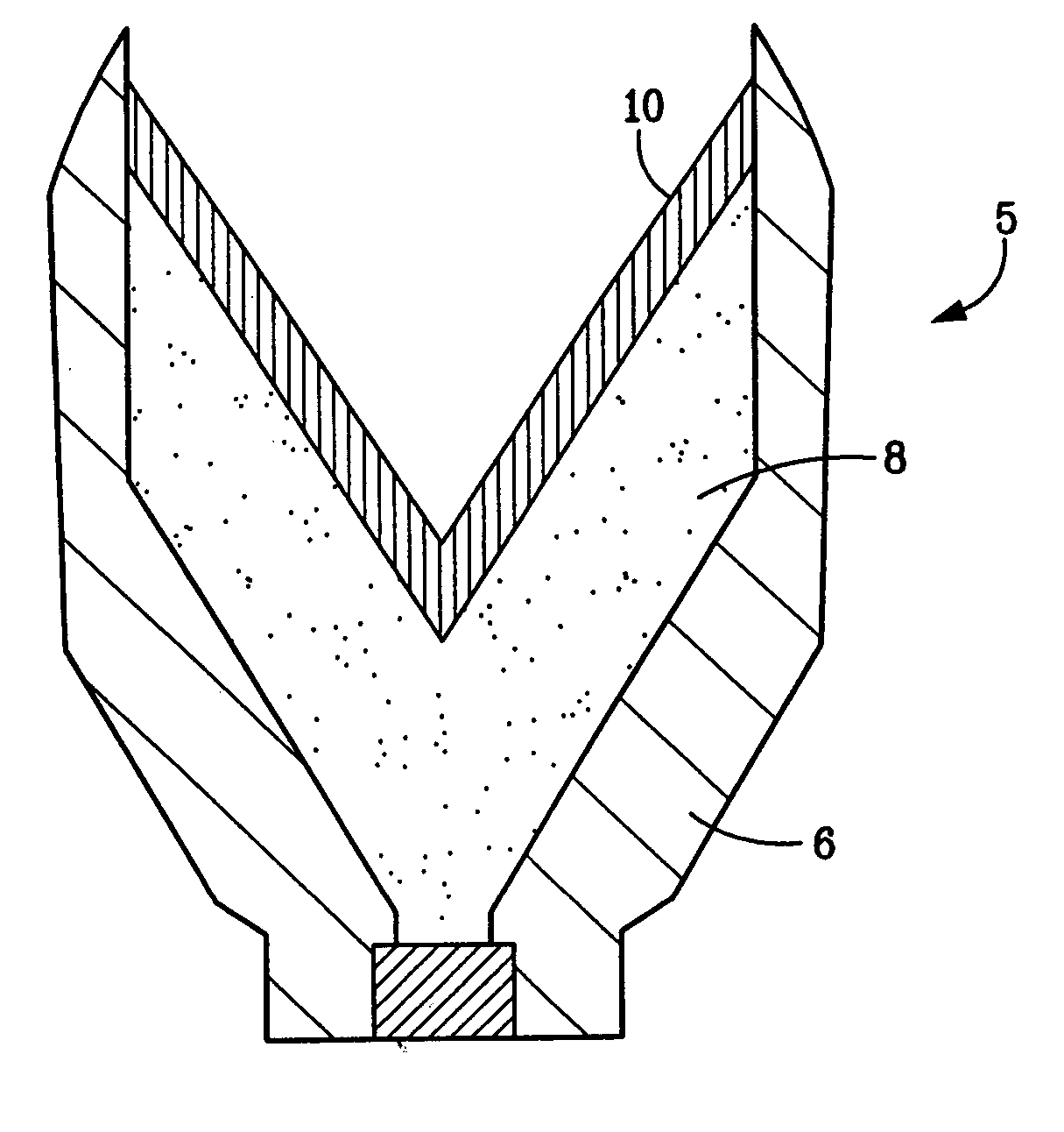
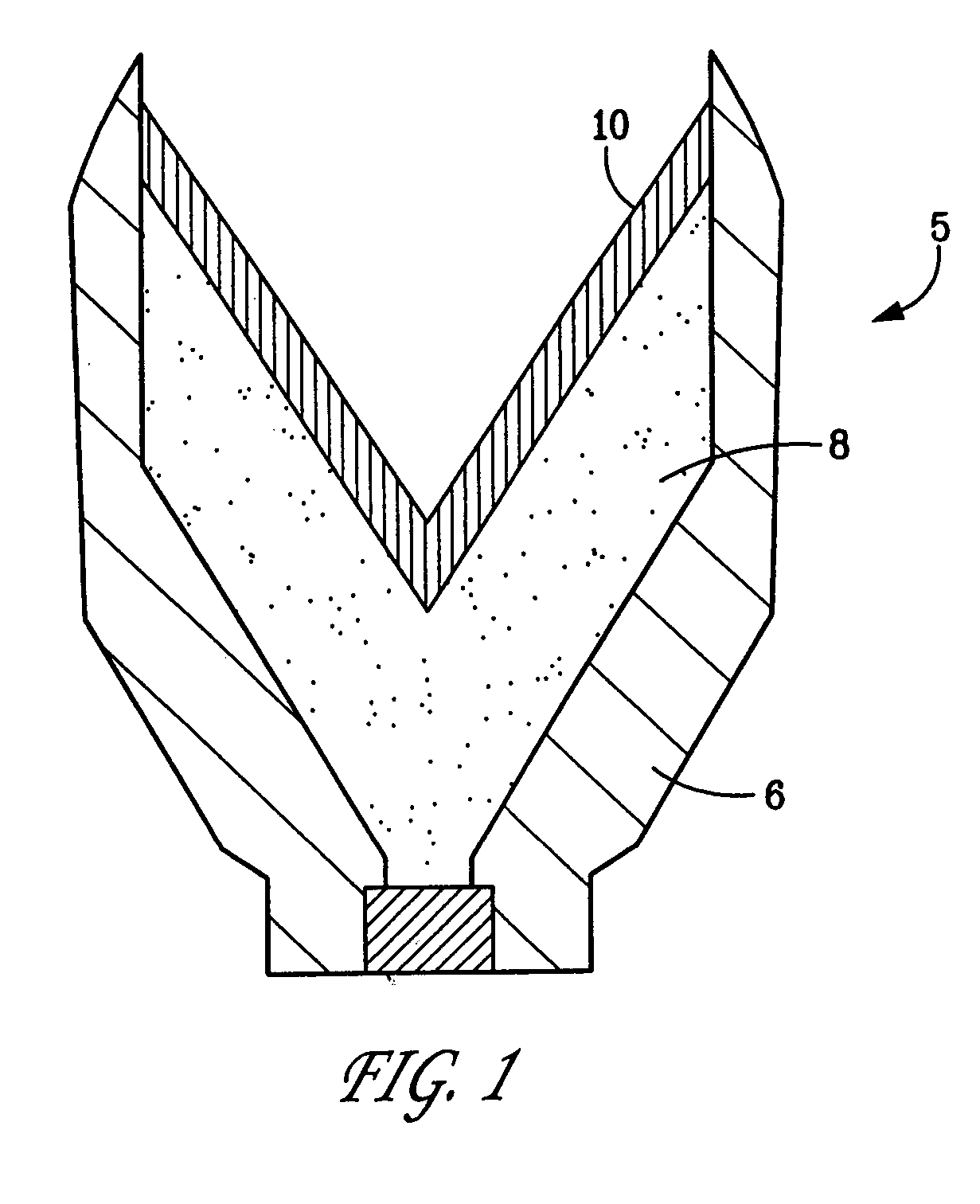
[0026] The present disclosure involves a shaped charge liner and a method of making the shaped charge liner. The method disclosed herein involves a form of metal injection molding wherein metal powders are mixed with binders and the mixture is subsequently injected under pressure into a mold. The binder is then removed during a de-binding process in order to form the final product.

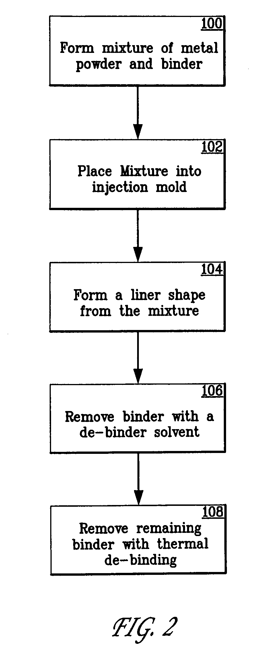
[0027] With reference now to FIG. 2, one embodiment of a method in accordance with the present invention is shown in flow chart form. Initially an amount of metal powder is combined with an amount of binder to form a mixture (step 100). The amount of metal powder of the mixture can range from about 20% up to about 100%, therefore the amount of binder will range from about 0% to about 20%. The particulate size of the powdered metal can range from about 1 micron to in excess of 70 microns. The powdered metal can be chosen from the list comprising: tungsten, uranium, hafnium, tantalum, nickel, copper, molybd...


PUM

PropertyMeasurementUnit
Shapeaaaaaaaaaa

Abstract

A shaped charge liner formed by injection molding, where the liner components include powdered metal and organic binder. The liner components are blended then processed within an injection molding device and urged from the molding device into a mold where a liner shape is formed. The liner shape is debinded, both mechanically and chemically. Mechanical debinding involves heating and chemical debinding comprises treating the liner shape with a solution to dissolve and remove the binder components. The process of forming the shaped charge liner does not include sintering. The present process can also use “green products” formed by the injection molding device that are not debinded. A shaped charge case can also be formed using the present method. The added step of sintering can be applied to the process of forming the shaped charge case.

Description

BACKGROUND OF THE INVENTION [0001] 1. Field of the Invention [0002] The invention relates generally to the field of oil and gas production. More specifically, the present invention relates to a method of producing a shaped charge liner from an injection molding process. [0003] 2. Description of Related Art [0004] Perforating guns are used for the purpose, among others, of making hydraulic communication passages, called perforations, in wellbores drilled through earth formations so that predetermined zones of the earth formations can be hydraulically connected to the wellbore. Perforations are needed because wellbores are typically completed by coaxially inserting a pipe or casing into the wellbore, and the casing is retained in the wellbore by pumping cement into the annular space between the wellbore and the casing. The cemented casing is provided in the wellbore for the specific purpose of hydraulically isolating from each other the various earth formations penetrated by the wellb...

Claims


Application Information

Patent Timeline
IPC IPC(8): B22F1/00F42B1/02
CPCE21B43/117F42B1/036F42B1/032
Inventor HETZ, AVIGDORLOEHR, JOHNWENDT, CLARENCE
Owner BAKER HUGHES INC
Learn More