
Gasification method and device for producing synthesis gases by partial oxidation of fuels containing ash at elevated pressure with partial quenching of the crude gas and waste heat recovery

a gasification method and ash technology, applied in the field of gasification, can solve the problems of high repair cost, rapid wear, and increase in wear process with increasing ash content, and achieve the effect of reliable operation and high availability

Inactive Publication Date: 2007-03-08
SIEMENS ENERGY GLOBAL GMBH & CO KG
View PDF8 Cites 23 Cited by
  • Summary
  • Abstract
  • Description
  • Claims
  • Application Information

AI Technical Summary

Benefits of technology

[0012] It is therefore an object of the invention, to provide a process that takes into account the different ash contents of fuels and has high availability, with reliable operation.
[0015] The hot crude gas leaves the gasification reactor together with the liquid slag formed from the fuel ash, and arrives at a chamber perpendicularly under it, in which partial quenching occurs by injecting water or by feeding in a cold gas and cooling to temperatures between 700° C. and 1,100° C. At this temperature, the entrained liquid slag has been cooled to the extent that it can no longer adhere to surfaces. The crude gas cooled to temperatures of 700° C. and 1,100° C. then arrives at a waste heat boiler together with the likewise cooled solid slag, to utilize the heat for steam production. This partial quenching or partial cooling prevents or sharply reduces the risk of slag caking on the waste heat cooling pipes. The water or recycled gas condensate needed for the partial quenching is fed in through nozzles that are located directly on the jacket. The cooled slag is collected in a water bath located at the bottom of the waste heat boiler. The crude gas, cooled to 200-300° C., leaves the waste heat boiler at the side and reaches a crude gas scrubber, preferably a Venturi scrubber.

Problems solved by technology

This has the drawback that the refractory masonry is loosened by the liquid slag formed during gasification, which leads to rapid wear and high repair costs.
This wear process increases with increasing ash content.
Thus such gasification systems have a limited service life before replacing the lining.
Also, the gasification temperature and the ash content of the fuel are limited.
Feeding in the fuel as a coal-water slurry causes considerable losses of efficiency; see C. Higman and M. van der Burgt, “Gasification”, Verlag ELSEVIER, USA, 2003.
This joint discharge of gasification gas and slag can lead to plugging of the conduit and thus to limitation of availability.
However, because of entrained liquid slag particles there is the danger of deposition and coating of heat exchanger surfaces, which hinders heat transfer and may lead to plugging of the pipe system and / or erosion.
A series of drawbacks detract from the advantage of waste heat recovery by this system; in particular, the formation of deposits on the heat exchanger tubes, which lead to hindrance of heat transfer and to corrosion and erosion, and thus to lack of availability.
This central discharge in the central pipe mentioned is susceptible to plugging that interferes with the overall operation, and reduces the availability of the entire system.

Method used


Image

  • Gasification method and device for producing synthesis gases by partial oxidation of fuels containing ash at elevated pressure with partial quenching of the crude gas and waste heat recovery
  • Gasification method and device for producing synthesis gases by partial oxidation of fuels containing ash at elevated pressure with partial quenching of the crude gas and waste heat recovery
  • Gasification method and device for producing synthesis gases by partial oxidation of fuels containing ash at elevated pressure with partial quenching of the crude gas and waste heat recovery

Examples


Embodiment Construction

[0023] 320 tons / hour of bituminous coal with a composition of

C71.5wt. %H4.2wt. %O9.1wt. %N0.7wt. %S1.5wt. %Cl0.03wt. %,

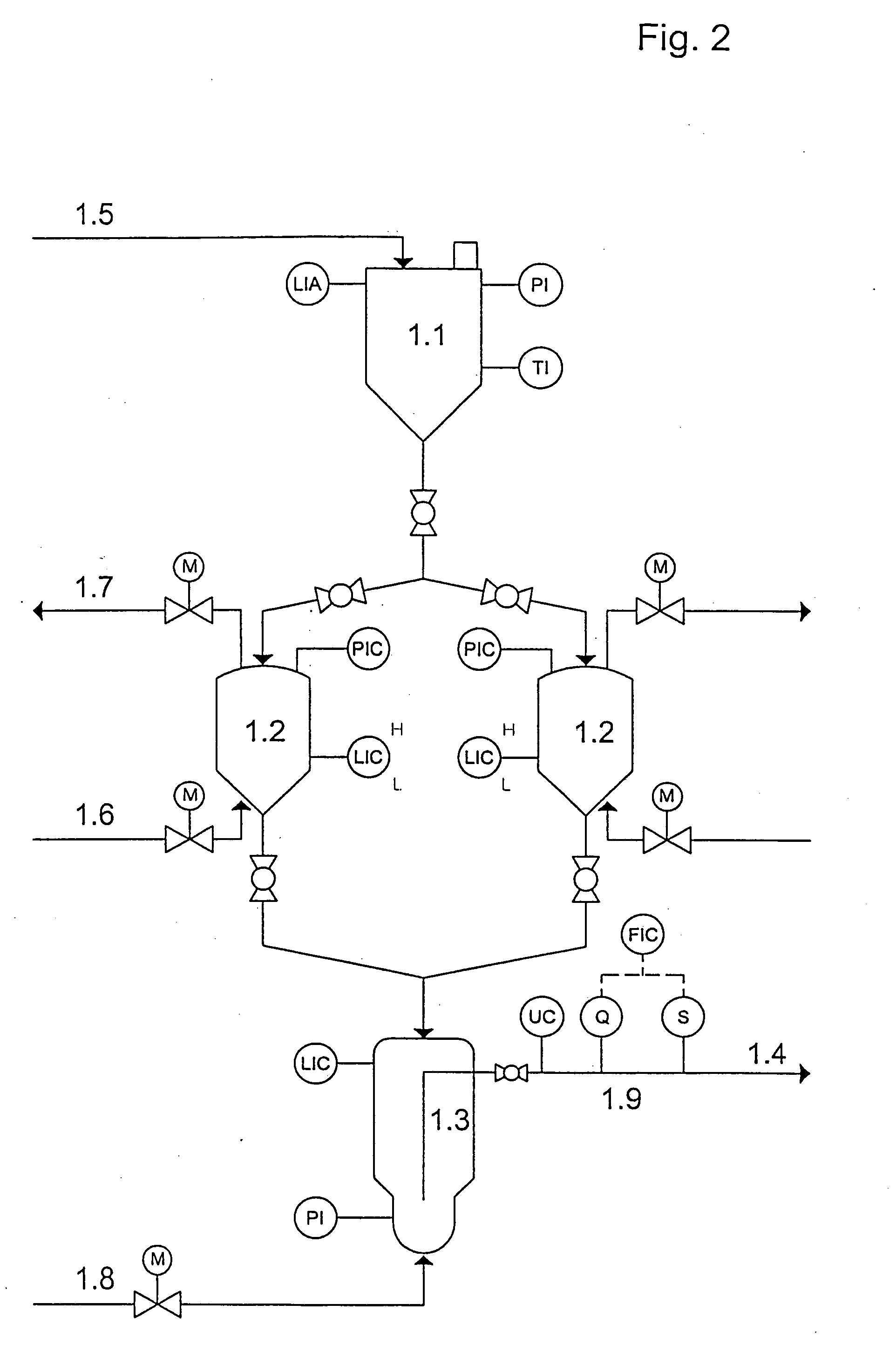
[0024] an ash content of 11.5 wt. %, and a moisture content of 7.8 wt. %, is to be gasified at a pressure of 40 bar. The calorific value of the coal is 25,600 kJ / kg. The gasification takes place at 1,450° C. 215,000 m3 I.H. / h of oxygen is needed for the gasification. The coal is first fed to a state-of-the-art drier and grinder in which its water content is reduced to 1.5 to the supply bunker 1.1 and is supplied alternately to the pressurized sluices 1.2. Suspension is carried out with an inert gas such as nitrogen, for example, that is fed in through the line 1.6. After suspension, the pressurized pulverized fuel is fed to the metering tank 1.3. The pressurized sluice 1.2 is depressurized through the line 1.7 and can again be filled with pulverized fuel. There are three pressurized sluices in place, which are filled and depressurized alternately. For the gasifica...


PUM


Abstract

A method and device for the gasification of solid fuels such as bituminous coal, lignite coal, and petroleum coke in the flue stream, with an oxidizing medium containing free oxygen by partial oxidation at pressures between atmospheric pressure and 80 bar, and at temperatures between 1200 and 1900° C., consisting of the process steps of pneumatic metering for pulverized fuel, gasification in a flue stream reactor with cooled reaction chamber contour, partial quenching, cooling, crude gas scrubbing, and partial condensation.

Description

BACKGROUND OF THE INVENTION [0001] 1. Field of the Invention [0002] This invention relates to a gasification method consisting of the process steps of fuel infeed, gasification reaction, partial quenching, waste heat recovery, gas scrubbing, and partial condensation, to produce gases containing CO and H2 by partial oxidation of pulverized fuels containing ash with a gasification medium containing free oxygen, at high temperatures and elevated pressure. [0003] To achieve long operating times, the pressurized jacket of the gasification reactor has to be protected reliably against the action of crude gas and against the high gasification temperatures of 1200-1900° C. This is done by confining the reaction or gasification chamber with a cooled tubular shield that is hung in the pressurized jacket. The annular gap between tubular shield and pressurized jacket is flushed. [0004] The fuel is fed to the head of the reactor through burners, using a pneumatic system following the flow transpo...

Claims


Application Information

Patent Timeline
IPC IPC(8): C10J3/00C10J1/207
CPCC10J3/466C10L5/366C10J3/721C10J3/84C10J3/845C10J2200/09C10J2200/156C10J2300/0903C10J2300/093C10J2300/0959C10J2300/1634C10J2300/1693C10K1/04C10K1/101C10L5/00C10J3/485Y02P20/129
Inventor HOLLE, BERNDSCHINGNITZ, MANFREDFISCHER, NORBERT
Owner SIEMENS ENERGY GLOBAL GMBH & CO KG
Learn More