
Use of nanoparticles in film formation and as solder

a technology of nanoparticles and film, applied in the direction of boron compounds, manufacturing tools, solventing apparatus, etc., can solve the problems of deficient material, electrical, thermal, chemical and optical properties at the bond, and limit the types of films that can be prepared on such substrates

Inactive Publication Date: 2007-03-01
NANOSYS INC
View PDF10 Cites 22 Cited by
  • Summary
  • Abstract
  • Description
  • Claims
  • Application Information

AI Technical Summary

Benefits of technology

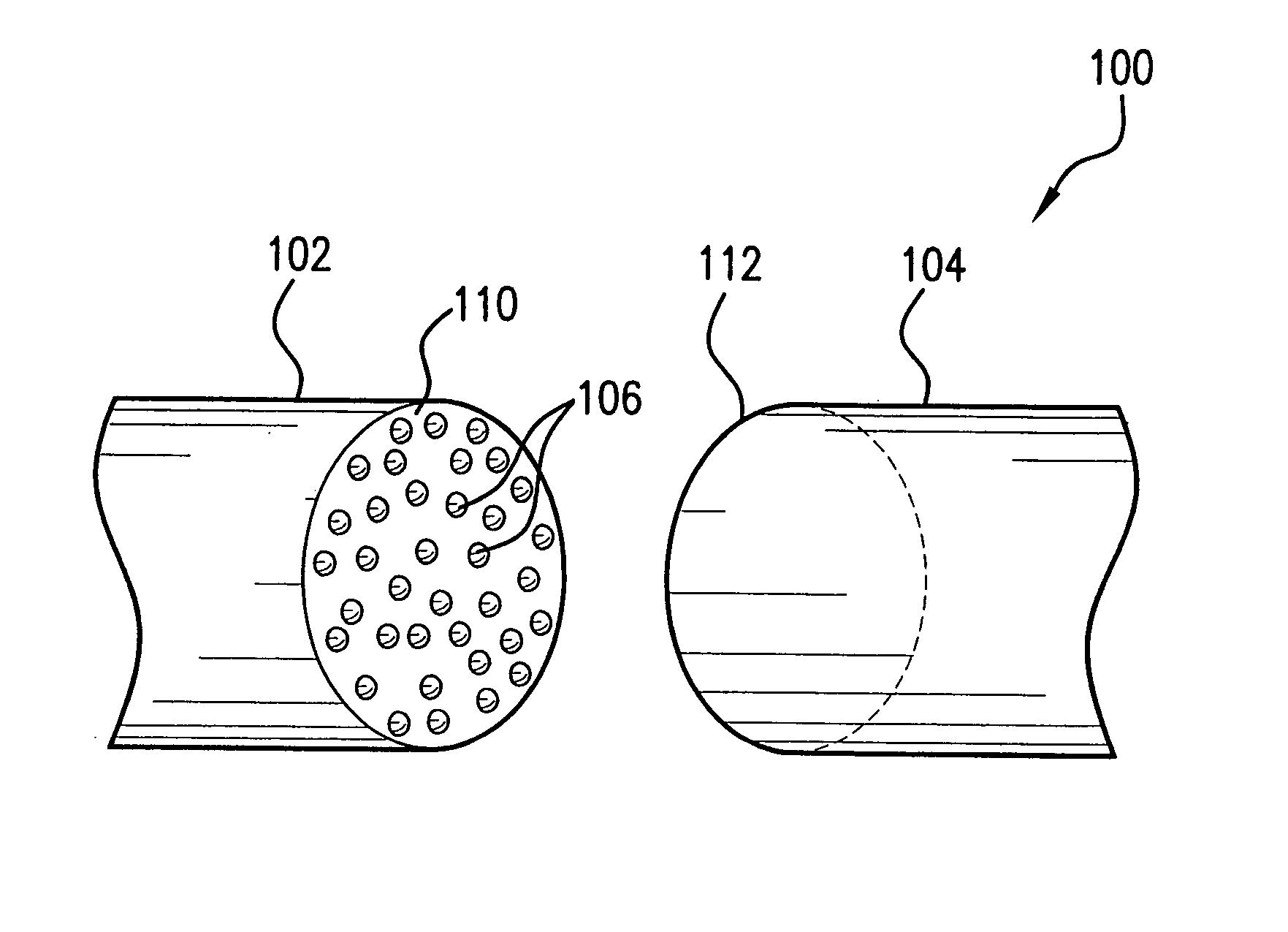
[0009] The present invention fulfills needs present in the art by providing nanoparticles for use as solder and methods of joining materials using the nanoparticle compositions. By using nanoparticles of selected sizes, alone or in the presence of additional gas species, a homogenous bond can be created between two materials, such that the various properties of the material are maintained at the bond site. The decreased melting temperature of the nanoparticles allow the nanoparticles to melt and form a bond while maintaining the structure of the bulk material being joined.
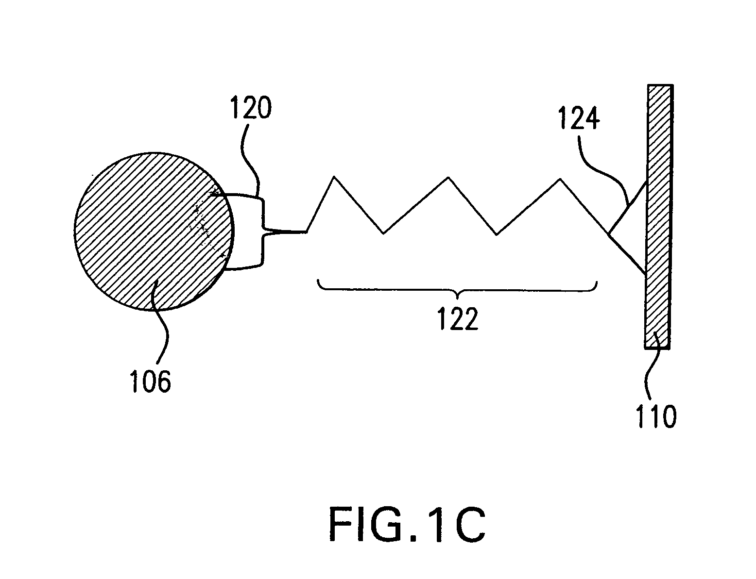
[0014] The present invention also provides a nanoparticle solder prepared by a process comprising: (a) providing nanoparticles, (b) layering the nanoparticles on a surface of a first material, and (c) heating the nanoparticles to a temperature where the nanoparticles melt, but the first material does not melt. The nanoparticles can comprise a ligand attached to their surface, and can be prepared from any of the materials, and in the various size ranges, disclosed throughout the present disclosure. In certain embodiments, a first gas species, such as hydrogen, can be provided during heating step (c). This gas species further lowers the melting temperature of the nanoparticles.

Problems solved by technology

This in turn can cause deficient material, electrical, thermal, chemical and optical properties at the bond.
In addition, as the melting temperature of certain polymeric (and other material) substrates is below that of many materials used in the construction of displays, radiofrequency identifiers and transistor backplanes, this limits the types of films that can be prepared on such substrates.

Method used


Image

  • Use of nanoparticles in film formation and as solder
  • Use of nanoparticles in film formation and as solder
  • Use of nanoparticles in film formation and as solder

Examples


Embodiment Construction

[0027] It should be appreciated that the particular implementations shown and described herein are examples of the invention and are not intended to otherwise limit the scope of the present invention in any way. Indeed, for the sake of brevity, conventional electronics, manufacturing, semiconductor devices, and nanocrystal, nanoparticle, nanowire (NW), nanorod, nanotube, and nanoribbon technologies and other functional aspects of the systems (and components of the individual operating components of the systems) may not be described in detail herein. Further, the techniques are suitable for applications in electrical systems, optical systems, consumer electronics, industrial or military electronics, wireless systems, space applications, or any other application.

[0028] As used herein, the terms “nanoparticle” and “nanocrystal” are used interchangeably. A nanoparticle has at least one region or characteristic dimension with a dimension of less than about 500 nm, including on the order...


PUM

PropertyMeasurementUnit
Diameteraaaaaaaaaa
Diameteraaaaaaaaaa
Diameteraaaaaaaaaa

Abstract

Nanoparticle compositions for use as solder, and methods for joining two or more material surfaces using nanoparticle solder compositions are described. Due to their small size, nanoparticles of a particular material have a lower melting temperature than the same material in bulk, thereby providing a homogenous bond between two or more materials when the nanoparticle solder is solidified. A gas species, such as hydrogen, can be introduced to further lower the melting temperature of the nanoparticles. The nanoparticles can also be used to form films on low melting point, substrates, including flexible substrates. The nanoparticles for use in the present invention can comprise any material, including semiconductor materials, metals, or insulator materials, and are less than about 20 nm in diameter, although larger sizes can also be used.

Description

CROSS REFERENCE TO RELATED APPLICATIONS [0001] The present application claims the benefit of the filing dates of U.S. Provisional Patent Application No. 60 / 679,990, filed May 12, 2005, U.S. Provisional Patent Application No. 60 / 730,886, filed Oct. 28, 2005 and U.S. Provisional Patent Application No. 60 / 735,157, filed Nov. 10, 2005, the disclosures of each of which are incorporated herein by reference in their entireties.BACKGROUND OF THE INVENTION [0002] 1. Field of the Invention [0003] The present invention relates to nanoparticle compositions for use in soldering applications and methods of soldering using nanoparticles. The present invention also relates to films formed from nanoparticles. [0004] 2. Background Art [0005] Nanoparticles and nanocrystals have gained a great deal of attention for their interesting and novel properties in electrical, chemical, optical and other applications. Such nanomaterials have a wide variety of expected and actual applications, including use as s...

Claims


Application Information

Patent Timeline
IPC IPC(8): H01S4/00
CPCB23K35/30B23K2101/40B23K35/3013B23K35/3033B23K35/3046B23K35/3053B23K35/3607B23K35/3608B82Y30/00H05K3/3484H05K3/3494H05K2201/0209H05K2201/0257H05K2203/087Y10T29/49002B23K35/3006H05K3/3485
Inventor CHEN, JIAN
Owner NANOSYS INC
Learn More