
Direct digital synthesizer system and related methods

a digital synthesizer and digital technology, applied in the field of direct digital synthesizers, can solve the problems of imposing restrictions on the designer, difficult or expensive to achieve using other frequency synthesis systems, and difficult to implement using direct frequency multiplication, phase-locked loops or direct digital synthesizers alone, etc., to avoid spurs

Inactive Publication Date: 2007-02-22
REVEAL IMAGING
View PDF9 Cites 30 Cited by
  • Summary
  • Abstract
  • Description
  • Claims
  • Application Information

AI Technical Summary

Benefits of technology

[0011] In view of the foregoing background, it is therefore an object of the present invention to provide a direct digital synthesizer operative in wide tuning applications and avoids spurs.

Problems solved by technology

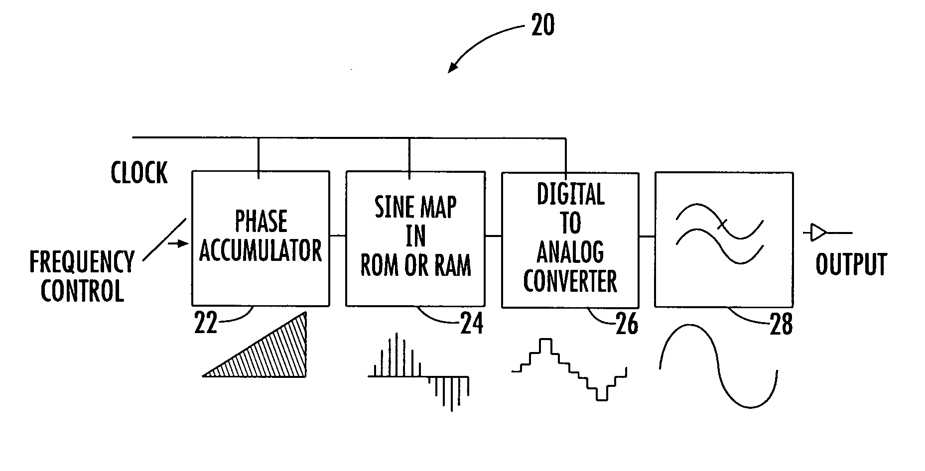
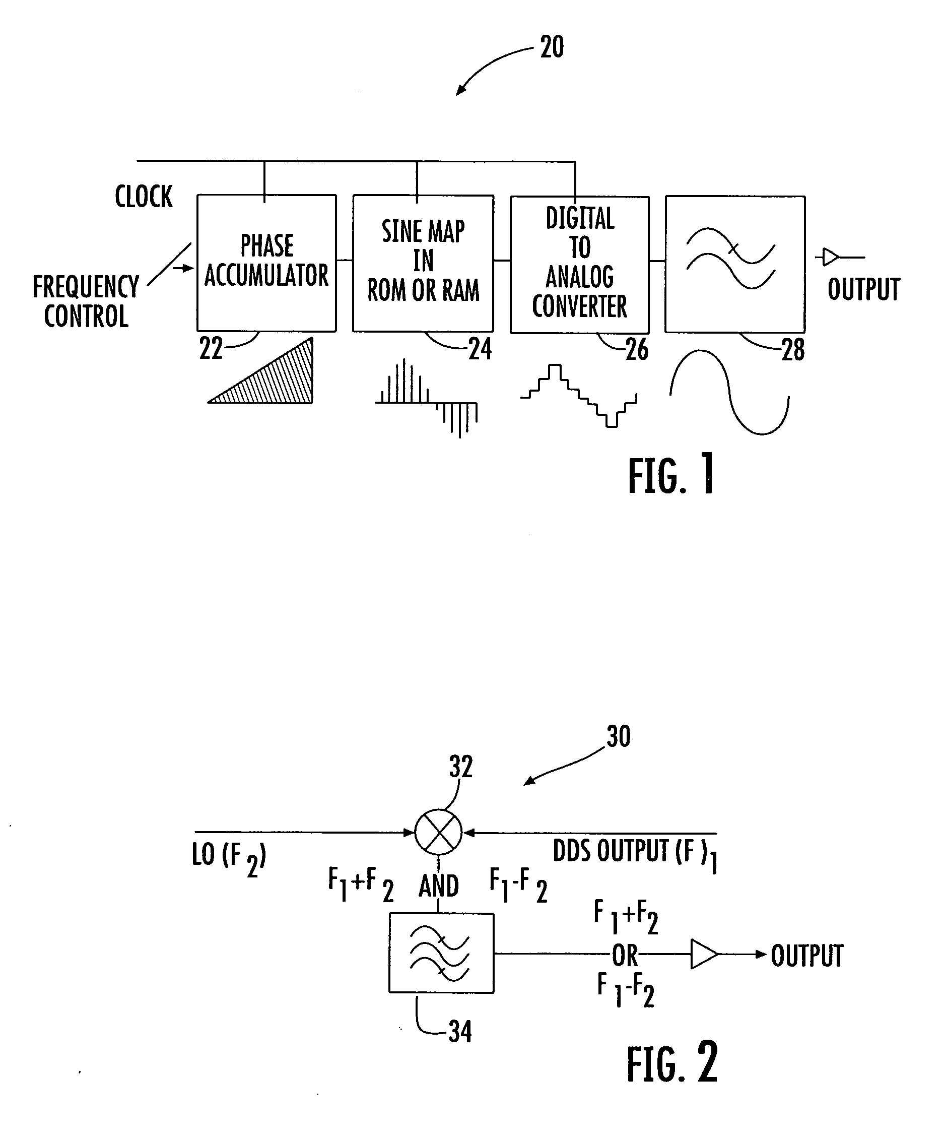
Many of today's communications and radar systems call for RF synthesizer performance, which often is difficult to implement using direct frequency multiplication, phase-locked-loop (PLL) or direct digital synthesizer (DDS) alone.
DDS provides advantages that are difficult or expensive to achieve using other frequency synthesis systems.
There are some disadvantages to common DDS systems, however, imposing some restrictions on the designer.
Another limitation is spectral purity, which is governed by the density / complexity of the logic circuitry that is attainable at the desired operating speed.
Despite these limitations, DDS is an important tool in many applications, and some of its functional capabilities are not attainable with most other signal generation techniques.
In some cases, designers do not accept the cost and complexity of multiple loop synthesizers when similar performance can be achieved by adding a DDS.
Spurs can sometimes be created by other source but these four sources are often more problematic.
In wide tuning applications, however, it is difficult to devise a frequency plan that avoids spurs.

Method used


Image

  • Direct digital synthesizer system and related methods
  • Direct digital synthesizer system and related methods
  • Direct digital synthesizer system and related methods

Examples


Embodiment Construction

[0027] The present invention will now be described more fully hereinafter with reference to the accompanying drawings, in which preferred embodiments of the invention are shown. This invention may, however, be embodied in many different forms and should not be construed as limited to the embodiments set forth herein. Rather, these embodiments are provided so that this disclosure will be thorough and complete, and will fully convey the scope of the invention to those skilled in the art. Like numbers refer to like elements throughout.

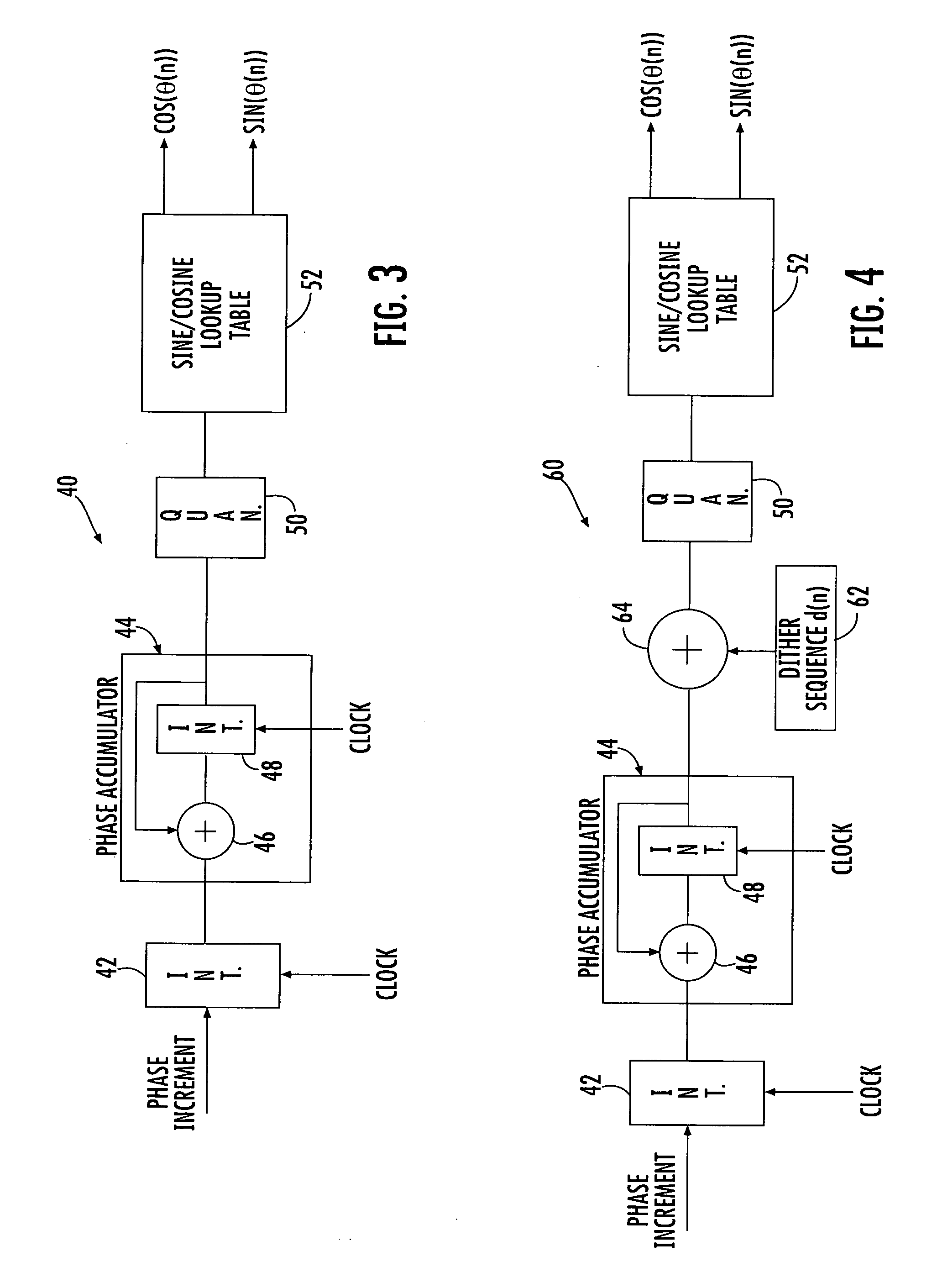
[0028] The DDS synthesizer of the present application uses frequency dither that suppresses spurs by breaking up the regularity of the output spectrum with randomization. Any line spectrum associated with the spurs is impressed on the final output waveform and results in spectral lines in the synthesizer output spectrum. This can be suppressed by breaking up the regularity of the output spectrum with randomization as frequency dither. In one non-limiting...


PUM


Abstract

A direct digital synthesizer (DDS) has reduced spurious signals and includes a DDS core that produces a digital representation of a signal to be synthesized. A plurality of DDS circuits are operatively connected to the DDS core, each having a digital-to-analog converter connected to the DDS core for receiving the digital representation and converting it into a signal. A modulator is operatively connected to an oscillator circuit and digital-to-analog converter for receiving signals from the digital-to-analog converter and producing a modulated output signal. The individual frequencies of the respective DDS circuits are randomly and continuously changed from each other. A mixer receives and mixes the modulated output signals from the plurality of DDS circuits to create a mixed output signal at a selected and fixed frequency.

Description

FIELD OF THE INVENTION [0001] This application relates to a direct digital synthesizer (DDS), and more particularly, to a direct digital synthesizer that suppresses spurs. BACKGROUND OF THE INVENTION [0002] Many of today's communications and radar systems call for RF synthesizer performance, which often is difficult to implement using direct frequency multiplication, phase-locked-loop (PLL) or direct digital synthesizer (DDS) alone. To achieve a desired frequency range, a high frequency output, a fine tuning resolution, a fast settling time, and a low phase noise, system designers often combine PLL and DDS technologies. The strengths of one technology join with the strengths of the other technology to extend the possible range of performance. [0003] DDS provides advantages that are difficult or expensive to achieve using other frequency synthesis systems. These advantages include fast switching (typically sub-microsecond), which is important in spread-spectrum or frequency-hopping s...

Claims


Application Information

Patent Timeline
Patent Type & Authority Applications(United States)
IPC IPC(8): H03L7/00
CPCG06F1/0328G06F1/0342G06F2211/902H03L7/16
Inventor AMMAR, DANNY F.
Owner REVEAL IMAGING
Learn More