[0013] The previously mentioned short-comings of prior art medical devices are addressed by the novel
medical device of the present invention. The medical device of the present invention can be designed to be inserted into a treatment site such that the medical device has improved procedural success rates and inhibits or prevents the occurrence of
thrombosis after the medical device has been inserted into the treatment area. The improved procedural success rate and the inhibition or prevention of the occurrence of
thrombosis by the medical device of the present invention can be achievable without the need for or with a significant reduction in need for aggressive anti-
platelet and / or anti-coagulation therapy after
insertion of the medical device in the treatment area. The improved
medical procedure of the present invention can be at least partially obtained by the use of a medical device that 1) is formed of one or more materials that enhances the physical properties of the medical device, and / or 2) includes one or more biological agents (e.g., anti-
platelet medication, etc.) that can be controllably and / or uncontrollably delivered at, adjacent to and / or into a treatment site by the medical device. The medical device in accordance with the present invention can be in the form of many different devices such as, but not limited to, stents, grafts, surgical grafts (e.g., vascular grafts, etc.), valves, orthopedic implants, sheaths,
guide wires,
balloon catheters, hypotubes, catheters (e.g.,
electrophysiology catheters,
guide catheter, stent
catheter, etc.),
cutting devices, PFO (
patent foramen ovale) device, sutures, staples, bandages, wraps,
biological glue, etc. In one non-limiting embodiment, the medical device is directed for use in a body passageway. As defined herein, the term “body passageway” is defined to be any passageway or cavity in a living
organism (e.g.,
bile duct, bronchiole tubes,
nasal cavity, blood vessels, heart,
esophagus, trachea,
stomach,
fallopian tube,
uterus,
ureter,
urethra, the intestines, lymphatic vessels, nasal passageways,
eustachian tube, acoustic meatus, etc.). The techniques employed to deliver the medical device to a treatment area include, but are not limited to,
angioplasty, vascular anastomoses,
transplantation, implantation, subcutaneous introduction, minimally invasive
surgical procedures, injection, topical applications, bolus administration, infusion, interventional procedures, and any combinations thereof. For vascular applications, the term “body passageway” primarily refers to blood vessels and chambers in the heart. When the medical device is in the form of a stent, the stent can be an expandable stent that is expandable by a
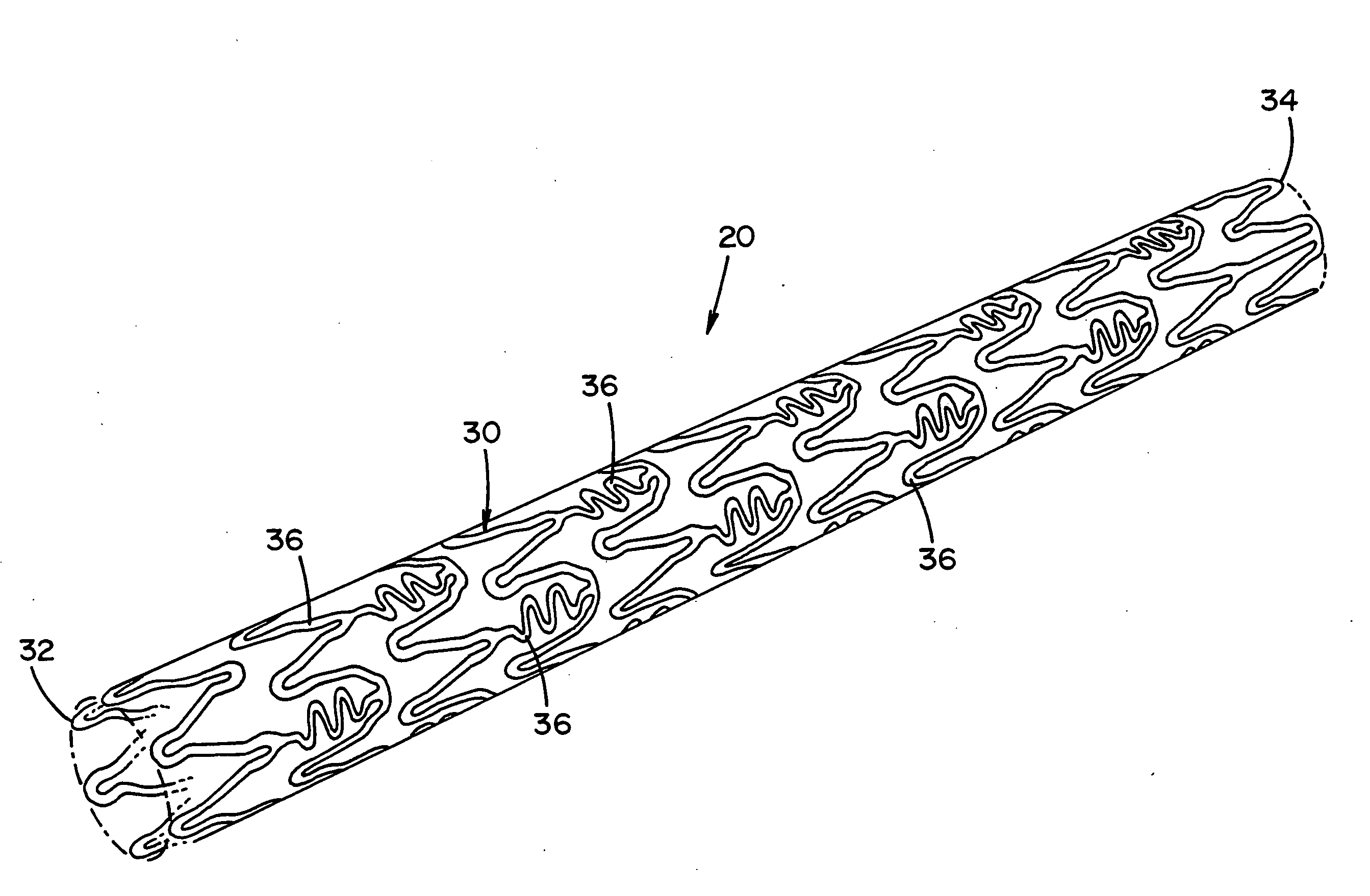
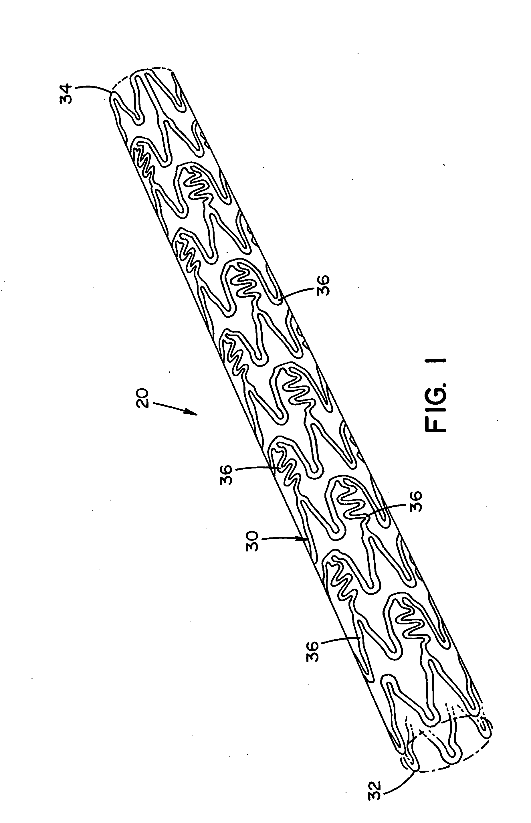
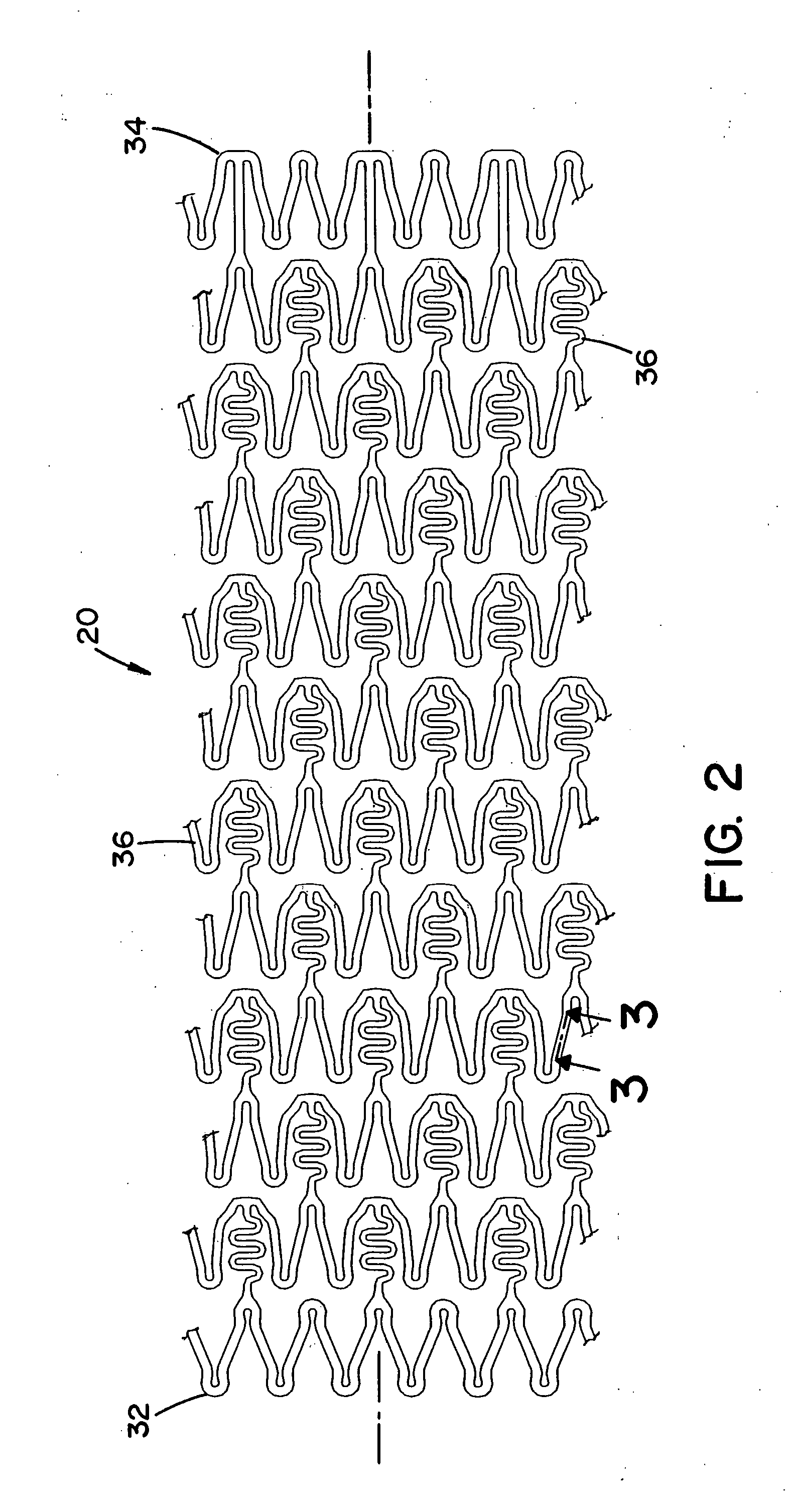
balloon and / or other means. The stent can have many shapes and forms. Such shapes can include, but are not limited to, stents disclosed in U.S. Pat. Nos. 6,206,916 and 6,436,133; and all the prior art cited in these patents. These various designs and configurations of stents in such patents are incorporated herein by reference.
[0014] In one non-limiting aspect of the present invention, the medical device has one or more features that at least partially result in the inhibition or prevention of thrombosis after the medical device has been implanted in a treatment area. These features include, but are not limited to, 1) the shape and / or profile of the medical device, 2) the one or more materials that are used to at least partially form the medical device, and / or 3) the one or more biological agents that are at least partially coated on, contained therein and / or included in the medical device. As a result, the need or use of body-wide standard aggressive anti-
platelet and / or anti-coagulation therapy for extended periods of time to inhibit or prevent the occurrence of thrombosis is not required in conjunction with the medical device of the present invention. In the past, the use of body-wide therapy was used by the patient long after the patient left the hospital or other type of medical facility. This body-wide therapy could last days, weeks, months or sometimes over a year after
surgery. The medical device of the present invention can be applied or inserted into a treatment area and 1) merely require reduced use of body wide therapy after application or insertion of the medical device, or 2) does not require use of body wide therapy after application or insertion of the medical device. As such, the medical device of the present invention can be designed to be inserted in a treatment area without any temporary use and / or without extended use of body wide aggressive anti-platelet and / or anti-coagulation therapy after the medical device has been inserted in the treatment area. This method of treating a treatment area with a medical device while inhibiting or preventing the occurrence of thrombosis at or near the treatment area is a significant improvement over past treatment procedures. In one non-limiting example, no body-wide therapy is needed after the insertion of the medical device into a patient. In another and / or alternative non-limiting example, short term use of body-wide therapy is needed or used after the insertion of the medical device into a patient. Such short term use can be terminated after the release of the patient from the hospital or other type of medical facility, or one to two days or weeks after the release of the patient from the hospital or other type of medical facility; however, it will be appreciated that other time periods of body-wide therapy can be used. As a result of the use of the medical device of the present invention, the use of body-wide therapy after a
medical procedure involving the insertion of a medical device into a treatment area can be significantly reduced or eliminated.


