
Method and a device for depositing a film of material or otherwise processing or inspecting, a substrate as it passes through a vacuum environment guided by a plurality of opposing and balanced air bearing lands and sealed by differentially pumped groves and sealing lands in a non-contact manner

Active Publication Date: 2007-02-08
NEW WAY MACHINE COMPONENTS
View PDF44 Cites 33 Cited by
  • Summary
  • Abstract
  • Description
  • Claims
  • Application Information

AI Technical Summary

Benefits of technology

[0013] An object of the present invention is to provide a method and apparatus for coating and baking FPD glass and semi-conductor substrates having a thin thickness and semi-uniform surface contained within an apparatus that allows for in-line processing and or controlled mini-environments for especially large panels in a substantially low pressure, or near perfect vacuum environment which greatly aides in the cleanliness, and non-contamination via particulates in the process of coating and baking said substrates.
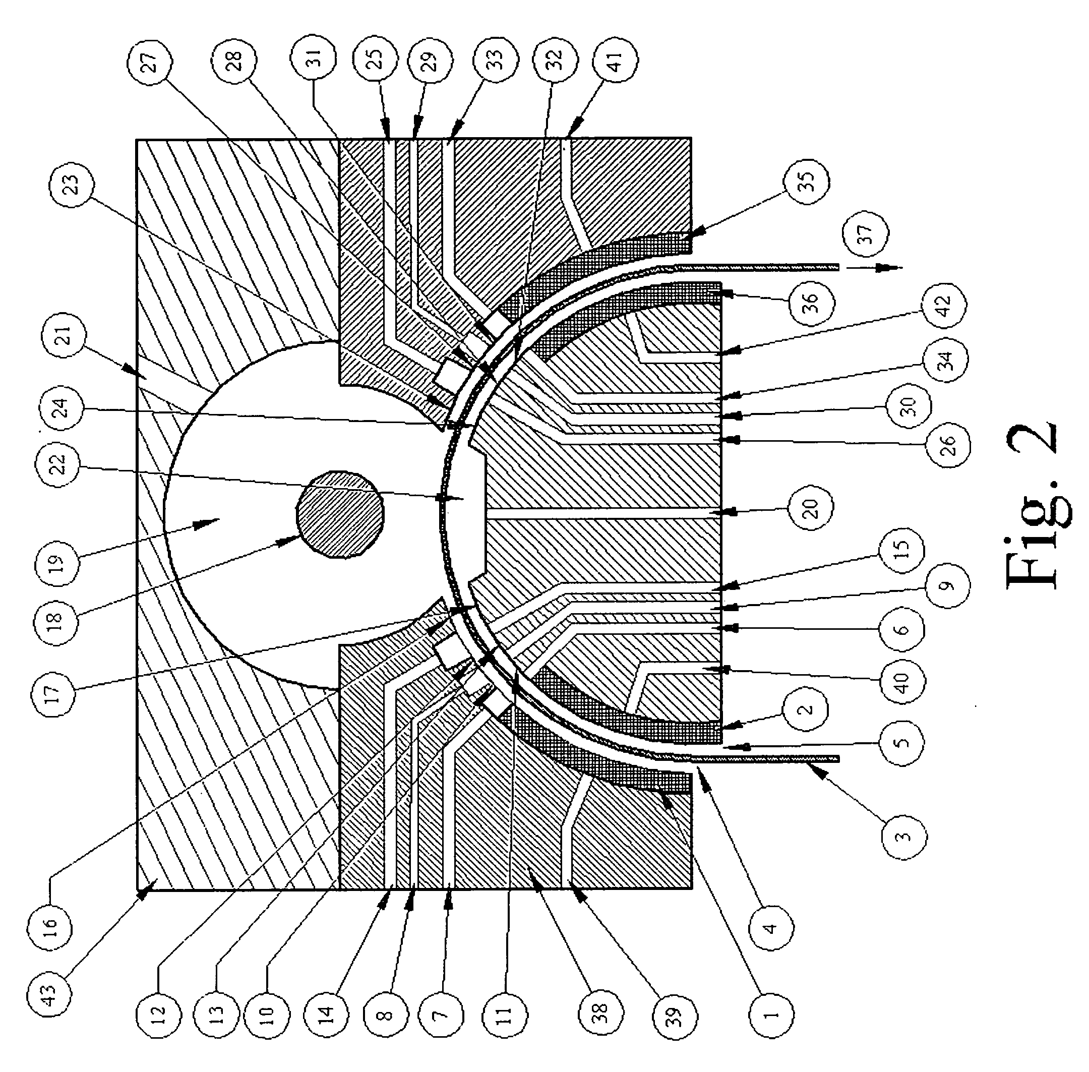
[0016] Through the use of successive differentially pumped grooves, axially placed relative to the substrate travel, a vacuum environment is created, as described in U.S. Pat. No. 6,515,288 Ryding, et al. enclosed herein as a reference, successive grooves are employed, leading to a chamber created by adding a larger cutaway in which a substantially lower pressure near vacuum is encapsulated and drawn down with external pumping means. This chamber allows an evaporative chemical vapor deposition (CVD) or plasma vapor deposition (PVD) process to be performed. The CVD / PVD process can be adjusted in order to deposit the desired thickness on the glass, or substrate. By heating the desired coating material, a type of gas is created, which causes particulate from the CVD / PVD process to condense on all surfaces within the chamber, including the desired substrate. Since there is a near perfect vacuum, there is no contamination via particulates or unwanted materials. The speed with which the substrate is moved through the apparatus can also be modulated in order to control the thickness. As the deposition process occurs, the substrate moves through the same number of differentially pumped grooves, only this time in increasingly higher levels of pressure, mirroring the initial series of grooves in reverse. In this way, a type of vacuum chamber is created within the middle of the process, insuring that outside ambient air is unable to penetrate, and appropriate vacuum pressures are reached as is required by the CVD / PVD process.
[0018] In yet a further embodiment of the described invention, a method can be integrated into the above described processes where the air supplied to the aerostatic bearings is temperature-controlled in preparation for a coating supplied by an axial slit type applicator. The aerostatic bearing on the top surface of the substrate is configured with numerous evenly placed holes along grooves longitudinally along the bearings, in the direction of the substrate processing direction. The holes supply a vacuum force which is substantially greater than the weight of the substrate, effectively pulling the glass against the aerostatic bearing lands for a precise gap between the bearing and the substrate. This enables the substrate to be introduced to the slit coater with micron level precision in the distance to the slit coater. This distance from the substrate to the coating orifice is important with certain types of coatings and insures an accurate thickness layer is applied. After the coating head, there are no longer any vacuum grooves in the aerostatic bearing which is holding the glass up against it; in fact the preferred embodiment is to have nothing near the substrate coating, so effectively a space is created within the apparatus, allowing the substrate coating to dry. The substrate is transported by a lower aerostatic bearing which supports the substrate as it is “handed off” from the upper aerostatic bearing, through the coater, then to be supported by the lower aerostatic bearing. This allows the coating to dry properly as well as avoid transcription effects which can occur should there be any temperature variations on the surface of the substrate during and after the coating process. The apparatus could then conceivably incorporate various drying and baking or further etching elements in order to enhance the coating performance.
[0021] The high heat source can, as described above, be situated on both sides of the substrate—above and below, and can be of numerous different means, as described immediately above. The simultaneous processing of both sides of the substrate in a non-contact nature of disposition is of great importance in some applications, and seen a major benefit of the invention, as well as the ability to perform rapid thermal processing and annealing.
[0023] Within the manufacturing arena, floor space of machinery used to process the FPD sheets or substrates within a clean room environment is costly due to the necessary processes required in maintaining such an environment. Any way to minimize the amount of floor space required is advantageous. For this reason, a further aspect of the apparatus is the inline coordination and inclusion of each element described above, the resulting savings in floor space within the clean room environment is substantial thereby realizing a large cost savings. Also the process is internal to the apparatus realizing significant benefits for the prevention of contamination of the clean room from any attendant aspects of any of the processes, as each stage can be performed on the substrate immediately after the previous one, insuring no contamination of the substrate passing from one operation to another.
[0024] Prior to this invention each step is performed separately, within the particular process's own arena on the manufacturing line, thereby requiring significant floor space and the attendant conveyance equipment required to safely transport the substrate between the manufacturing processes. A further aspect of the preferred embodiment entails the processing of substrates and especially large substrates in processes as described above but in an immediately sequential fashion. This includes individually sequential ordering but also is to include simultaneous processing, so that a substrate conceivably could have any number of processes being performed at once, which is especially useful for web type substrates. Such improvements are perceived by its inventor as a significant enhancement in a growing industry which can potentially realize large cost savings while improving overall processes parameters at the same time.

Problems solved by technology

The processing of these sheets is expensive in that their increasing size makes handling difficult regarding the brittle nature of the glass, due to its thin cross section—precluding anything but the gentlest method of transference.
Further increasing the difficulty in processing is the need to perform some operations in a vacuum environment to insure non-contamination of the coating process.
This is unsatisfactory since the thickness of the coating and the processing parameters need to be controlled for precision applications, also since the size of the apparatus required for ever larger generations of glass is prohibitive, since such equipment must be operated in a clean room environment in order to prevent contamination from particles.
Substrates can be dipped and or sprayed as well—neither of which is suitable for FPD glass, or semi-conductor industry products due to handling issues and a lack of assurance of non-contamination.
Very precise thickness coatings can be attained in this manner, however the size of the FPD glass, and some Integrated Circuits and wafers pose a problem regarding the subsequent size of the vacuum vessel needed to accommodate these substrates.
Also, the processing time required to create the vacuum environment for larger panels is deleterious to lower cost processing and ease of application.
This process also must take place in a clean room, the floor space for which is expensive.
Problems associated with un-even heating arise in that if the heat source is not applied evenly to the substrate surface, warping and or variations in the surface quality can occur, as well as areas where there is more rapid evaporation of the rinse water from the cleaning process, leaving behind streaks and or water spots.
Still further, baking presents problems to the cleanliness of the clean room environment, since the presence of high heat sources can create unwanted particulate and contamination in clean room environments through the opening and closing of the chamber used to heat the substrates.

Method used


Image

  • Method and a device for depositing a film of material or otherwise processing or inspecting, a substrate as it passes through a vacuum environment guided by a plurality of opposing and balanced air bearing lands and sealed by differentially pumped groves and sealing lands in a non-contact manner
  • Method and a device for depositing a film of material or otherwise processing or inspecting, a substrate as it passes through a vacuum environment guided by a plurality of opposing and balanced air bearing lands and sealed by differentially pumped groves and sealing lands in a non-contact manner
  • Method and a device for depositing a film of material or otherwise processing or inspecting, a substrate as it passes through a vacuum environment guided by a plurality of opposing and balanced air bearing lands and sealed by differentially pumped groves and sealing lands in a non-contact manner

Examples


Embodiment Construction

[0029] As will be understood by those skilled in the art, the present invention may be embodied in other specific forms or configurations without departing from the essential characteristics or spirit and scope thereof. Accordingly, the foregoing description is intended to be illustrative, but not limiting, of the scope of the invention which is set forth in the following claims. Thus it is intended that the present invention cover the modifications and variations of this intention provided they come within the scope of the appended claims and their equivalents.

[0030] Coating / Baking—Flat Substrate

[0031] In the preferred embodiment, FIG. 1 represents the coating of a substrate, such as a Chemical Vapor Deposition (CVD) method. This method requires a vacuum in order to be viable, and as is disclosed in U.S. Pat. No. 6,163,033 Smick (enclosed herein for reference) the use of differentially pumped grooves, for forming a moving dynamic seal and is here so employed. A substrate 3, such ...


PUM

PropertyMeasurementUnit
Temperatureaaaaaaaaaa
Thicknessaaaaaaaaaa
Pressureaaaaaaaaaa

Abstract

A method and apparatus for coating and baking and deposition of surfaces on glass substrate or flexible substrate, such as films and thin glass sheets or other similar work pieces as it transitions thru and between small gaps of aero-static or hydro-static porous media bearings and differentially pumped vacuum grooves, in a non-contact manner, in order to process within a vacuum environment. The process is also intended to incorporate simultaneous and immediately sequential ordering of various processes.

Description

REFERENCE TO RELATED APPLICATION [0001] The present application claims the benefit of U.S. Provisional Patent Application No. 60 / 704,453, filed Aug. 2, 2005, whose disclosure is hereby incorporated by reference in its entirety into the present disclosure.FIELD OF THE INVENTION [0002] The present invention relates to a coating, baking and deposition apparatus for the semi-conductor industry, solar elements, as well as the precision panel substrate elements, film substrate industry, integrated circuit, and panel circuit boards also such other like devices and substrates arise, the usefulness of the present invention in those applications will be readily apparent. Description of Related Art [0003] In the FPD industry ever larger sheets of glass are being employed in the manufacture of Flat Panel Displays. The processing of these sheets is expensive in that their increasing size makes handling difficult regarding the brittle nature of the glass, due to its thin cross section—precluding ...

Claims


Application Information

Patent Timeline
IPC IPC(8): C23C16/00
CPCC03B35/147H01L21/67739C03C17/002C03C23/0075C23C14/562C23C16/4409C23C16/545F16C33/748F16C2300/62H01J37/3277H01J37/32834H01L21/67028H01L21/67034H01L21/67051F16C32/0614B05C13/00C23C16/458C23C16/50C03C15/00Y02P40/57
Inventor DEVITT, ANDREW J.
Owner NEW WAY MACHINE COMPONENTS
Learn More