
Method and apparatus for manufacturing nitrogen trifluoride

Active Publication Date: 2007-02-08
FOOSUNG
View PDF20 Cites 3 Cited by
  • Summary
  • Abstract
  • Description
  • Claims
  • Application Information

AI Technical Summary

Benefits of technology

[0035] The present invention efficiently produces high yields of NF.sub.3 in a novel reactor without significant mechanical agitation in which F.sub.2 and NH.sub.3 are introduced into the reactor through conduits or nozzles into liquefied, less acidic AAF reactant (NH.sub.4F·x HF where the ratio of NH.sub.3 to HF is approximately 1:2.28-1:2.55). This maximizes Reaction 1 over the competing reactions and optimizes selectivity of the production of NF.sub.3 to the production of undesired byproducts.
[0038] The nozzles used for the introduction of F.sub.2 and NH.sub.3 and the pipes used for withdrawal of NF.sub.3 and AAF can be formed from any material compatible with the reactants and the product and co-products. A small amount of added mechanical mixing may be utilized in accordance with the method described here in (up to about 5000 wafts per cubic meter of reactor volume) but without vigorous mixing. Any cooling media sufficient to remove the heat of reaction is satisfactory.
[0049] The results show that the addition of static mixers dramatically improves selectivity and yield to levels that meet or exceed those achieved by the prior art without the energy cost of agitation (up to 35,000 watts per cubic meter), and without the mechanical complexity, high corrosion rates and increased operational cost of an agitated reactor. Example 3
[0052] The results show that increased reactor diameter dramatically improves selectivity and yield to levels well in excess of those achieved by the prior art.

Problems solved by technology

Reaction 3 produces N.sub.2F.sub.2, which is unstable and a significant safety hazard, and large quantities of undesired HF.
Reaction 4 results from poor quality NH.sub.3 and F.sub.2.

Method used


Image

  • Method and apparatus for manufacturing nitrogen trifluoride

Examples


Embodiment Construction

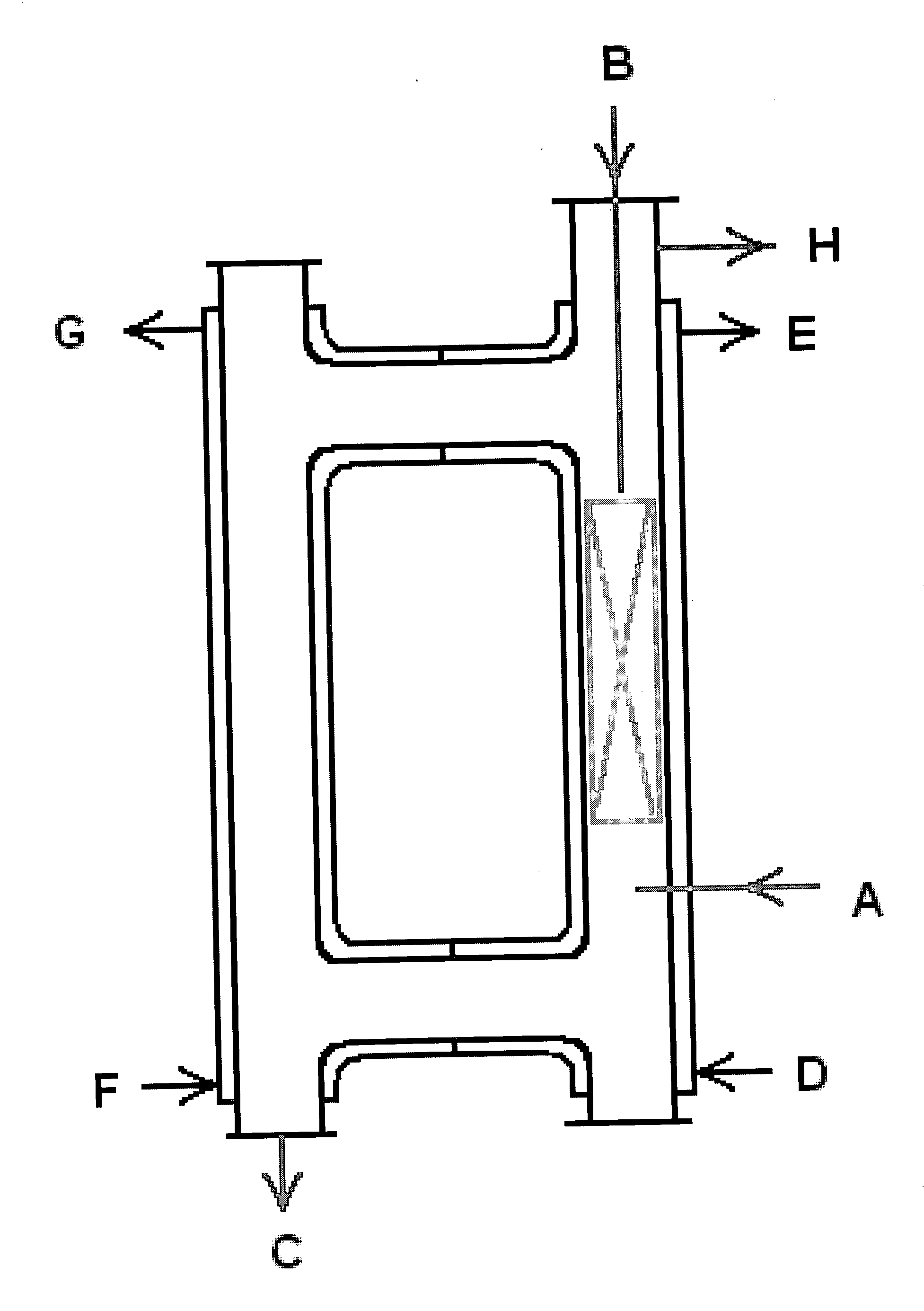
[0059] The preferred embodiment of the method and apparatus for producing NF.sub.3 set forth in the summary above is a closed-loop, stainless steel reactor of approximately 0.616 cubic meters with an inner diameter of approximately 8 inches employing one or more static mixing elements, preferably about 8 to 10 static mixing elements, between points A and B shown on FIG. 1 across approximately 30%-40% of the length of the reactor, operating at a temperature of approximately 5.degree.C. higher than the melting point of the AAF, but in all cases less than approximately 140.degree.C., optimally, approximately 120.degree.C. to 137.degree.C. The reactor operates at a pressure of 4 to 5 kilograms per square centimeter.

[0060] F.sub.2 is introduced at point A on FIG. 1. NH.sub.3 (ideally, high purity anhydrous ammonia) is introduced at point B of FIG. 1. The static mixing elements, optimally between 8 and 10, are located between points A and B on FIG. 1 across approximately 30%-40% of the l...


PUM


Abstract

A method and apparatus for manufacture of NF.sub.3 by gas-liquid phase reaction of fluorine and ammonia in molten ammonium acid fluoride (AAF) in a static reactor in which the reactants are conveyed primarily by thermal conduction or siphon. Optimally, the reactor contains one or more static mixing elements with little, if any, mechanical agitation. Reactant flow rate and reaction temperature are regulated by the rate of introduction of ammonia and cooling, as necessary The ratio of hydrogen fluoride (generated by the reaction) to ammonia in the reactor is significantly lower than taught in the prior art. This allows a lower reaction temperature. The present invention is an improved synthetic method that offers enhanced selectivity and higher yields, improved control of reaction kinetics, reduced operational and energy costs, and a greater margin of safety.

Description

BACKGROUND OF THE INVENTION [0001] The present invention is directed to a method and apparatus for the manufacture of nitrogen trifluoride (NF.sub.3) by reacting elemental fluorine (“F.sub.2”), gaseous ammonia (“NH.sub.3”) and a molten ammonium acid fluoride (“AAF”). In the preferred embodiment, the method and apparatus concurrently produces co-product ammonium bifluoride (NH.sub.4HF, “ABF”) that is salable after removal of excess hydrogen fluoride (“HF”). [0002] The reaction is accomplished in a static reactor without significant mechanical agitation that may contain static mixing elements and that may be configured in a closed loop. The present invention increases reaction selectivity and yield of nitrogen trifluoride while minimizing creation of undesired and unstable by-products and, simultaneously, reducing operational costs and improving control over reaction kinetics. [0003] In the preferred embodiment, flow of reactants is accomplished without adding significant energy to th...

Claims


Application Information

Patent Timeline
IPC IPC(8): C01B21/06
CPCC01B21/0835
Inventor IIKUBO, YUICHI
Owner FOOSUNG
Learn More