
DLL-based programmable clock generator using a threshold-trigger delay element circuit and a circular edge combiner

Inactive Publication Date: 2007-02-08
IND TECH RES INST
View PDF4 Cites 34 Cited by
  • Summary
  • Abstract
  • Description
  • Claims
  • Application Information

AI Technical Summary

Benefits of technology

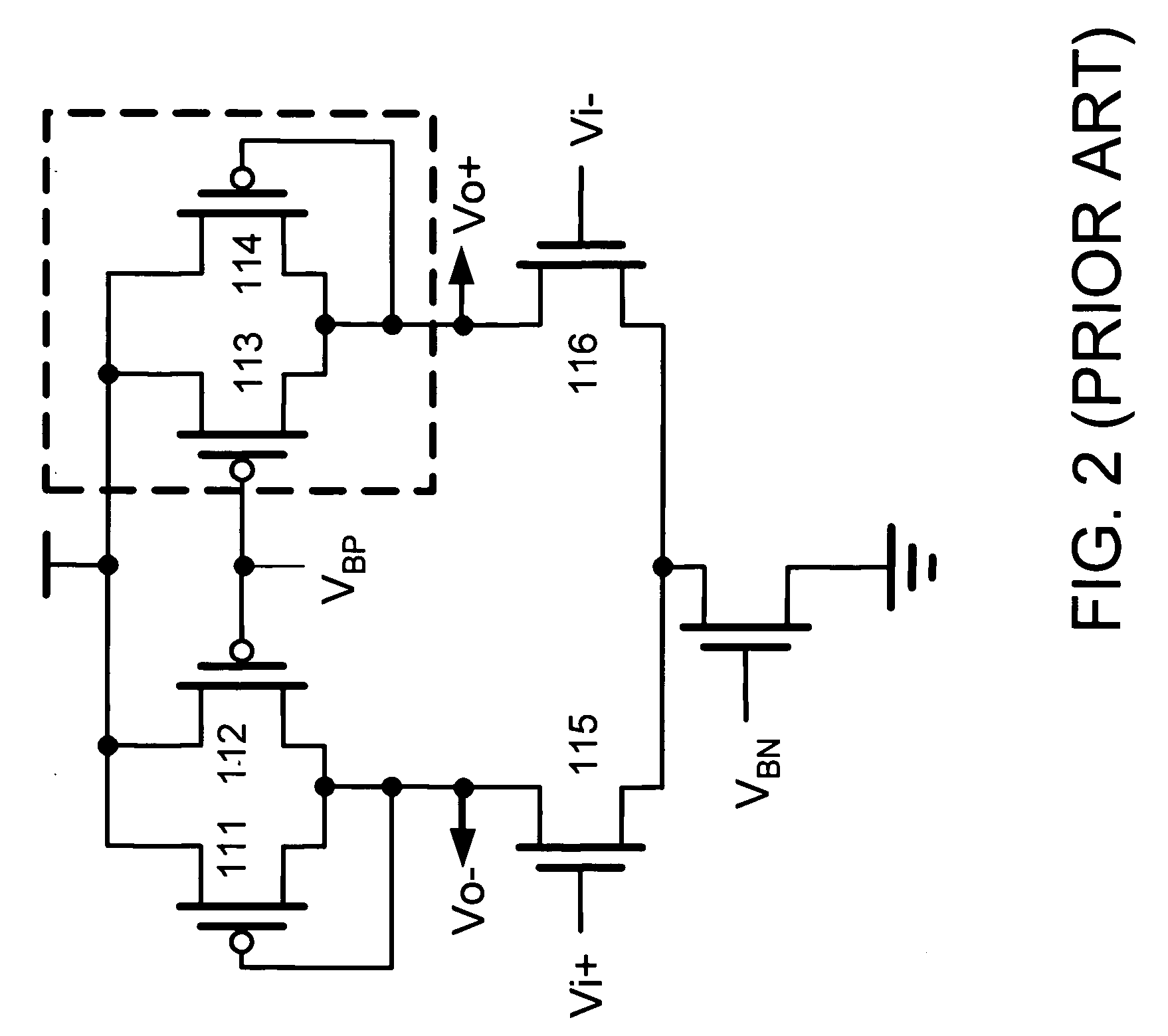
[0014] The delay element consumes no DC power and performs full output swing. It exhibits small delay jitter resulting reduced out jitter. It also increases the linearity of delay time versus control voltage. An edge combiner using double edge scheme may overcome the drawbacks of the circuit in the prior art to reduce minimum supply voltage and perform symmetrical rise and fall time.
[0015] According to the clock generator of the embodiment, a programmable circuit is designed with balanced loading on all delay paths of multi-phase signals to reduce output clock jitter.

Problems solved by technology

It also increases the linearity of delay time versus control voltage.

Method used


Image

  • DLL-based programmable clock generator using a threshold-trigger delay element circuit and a circular edge combiner
  • DLL-based programmable clock generator using a threshold-trigger delay element circuit and a circular edge combiner
  • DLL-based programmable clock generator using a threshold-trigger delay element circuit and a circular edge combiner

Examples


Embodiment Construction

[0033] Reference will now be made in greater detail to a preferred embodiment of the invention, an example of which is illustrated in the accompanying drawings. The following description of the preferred embodiment(s) is merely exemplary in nature and is in no way intended to limit the invention, its application, or uses. For purposes of clarity, the same reference numbers will be used in the drawings to identify similar elements. Wherever possible, the same reference numerals are used throughout the drawings and the description to refer to the same or like parts. Reference in the specification to “one embodiment” or “an embodiment” means that a particular feature, structure, or characteristic described in connection with the embodiment is included in at least one embodiment of the invention. The appearances of the phrase “in one embodiment” in various places in the specification are not necessarily all referring to the same embodiment.

[0034] Referring now to FIG. 5, illustrating a...


PUM


Abstract

A DLL-based programmable clock generator using a threshold-trigger delay element and an edge combiner is proposed. A threshold-trigger delay element with full swing complementary output signals consumes no dc power. It exhibits small delay error resulting reduced out jitter. It also increases the linearity of delay time versus control voltage. The circular edge combiner can multiply the input signal at a lower supply voltage. The rise and fall time of output signal are more symmetrical. It also present the multiplication factor of the clock generator can be easy to choose with the increasing of the number of delay elements.

Description

FIELD OF THE INVENTION [0001] The present invention relates to a clock generator, and more particularly, to a clock generator using a threshold-trigger delay element circuit and a circular edge combiner. BACKGROUND OF THE INVENTION [0002] A clock generator is essential in modern computer systems and consumer products. A clock generator with a delay-locked loop (DLL) may be employed in a computer system as a clock generator or radio communication as a clock synthesizer. Most clock generators adopt phase-locked loop (PLL) scheme; however, a delay-locked loop (DLL) having features of low jitter, better stability and small area is more suitable than a phase-locked loop as a clock multiplier. [0003] A traditional DLL-based clock generator 100 is illustrates in FIG. 1. A reference frequency Fin is delivered into the voltage control delay line 101 and the phase detector 102. The phase detector 102 detects the phase of the input frequency Fin and generates control signals to the charge pump...

Claims


Application Information

Patent Timeline
IPC IPC(8): H03L7/06
CPCH03K5/133H03K2005/00026H03L7/16H03L7/0812H03L7/0891H03K2005/00052H03L7/0816
Inventor HUANG, HONG-YISHEN, JIAN-HONGCHU, YUAN-HUA
Owner IND TECH RES INST
Learn More