Fast peak detector circuit

a detector circuit and peak detector technology, applied in the direction of pulse technique, instant pulse delivery arrangement, instruments, etc., can solve the problems of not working well for fast signals, operational amplifier going into saturation, etc., and achieve the effect of fast charging

Inactive Publication Date: 2007-02-08
GERSHFELD JACK
View PDF8 Cites 8 Cited by
  • Summary
  • Abstract
  • Description
  • Claims
  • Application Information

AI Technical Summary

Benefits of technology

[0006] The fast peak detector circuit of the present invention satisfies the above need. Specifically, the present invention utilizes three additional components to bootstrap the operational amplifier and to isolate and provide feedback for the circuit, namely, a buffer operational amplifier, a strap diode and feedback resistor. An alternative embodiment of this invention utilizes a transistor instead of a strap diode to provide faster charging for Hold Capacitor through current gain action of the transistor.

Problems solved by technology

However, it does not work well for fast signals, such as video signals.
The limitation comes from the operational amplifier going into saturation during negative cycles of the signal.
Once in the saturation mode, it takes a very long time for the operational amplifier to recover and return to the active region and trace the incoming signal.
However, it will take significant amount of time for the operational amplifier to recover from −5 Volts back to 1 Volt.

Method used


Image

  • Fast peak detector circuit
  • Fast peak detector circuit
  • Fast peak detector circuit

Examples


Embodiment Construction

[0009] This invention will be better understood with the reference to the drawing figures FIG. 3 and FIG. 4. The same references pertain to the same elements in all drawing figures.

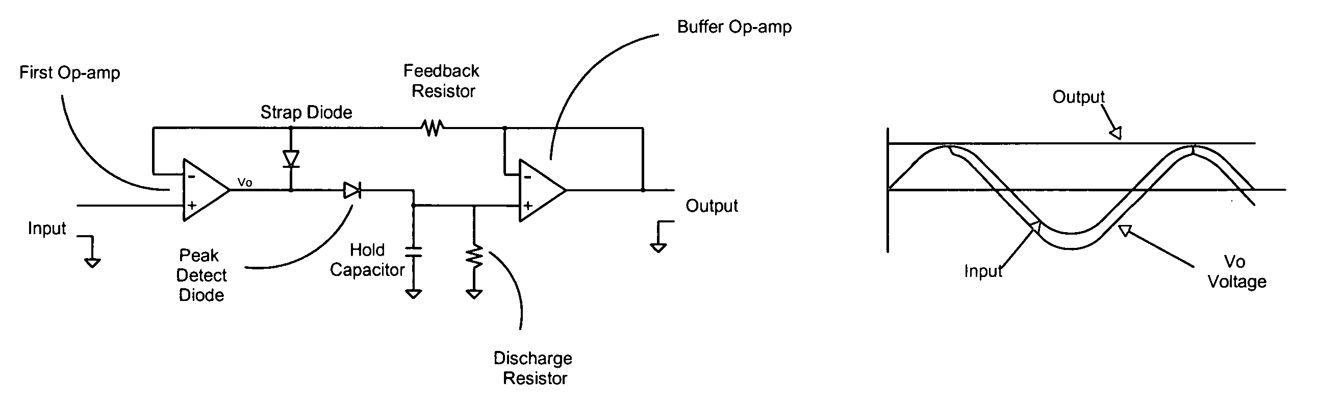
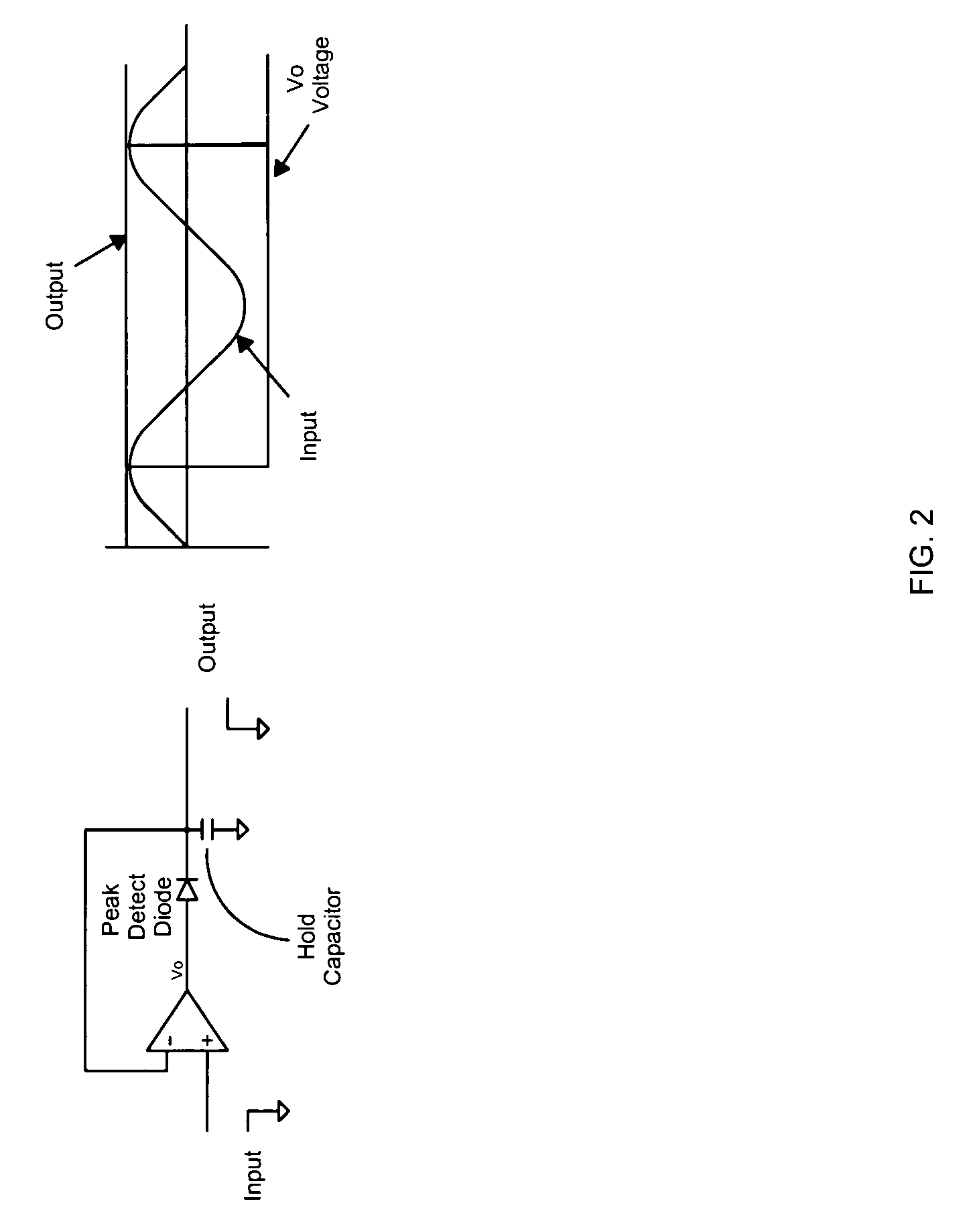
[0010] Viewing FIG. 3, there is shown a schematic representation of the fast peak detector according to the first embodiment of this invention, as well as the graph that illustrates the operation of said embodiment. The referenced “First Op-amp” indicates a first operational amplifier. First Op-amp has first and second inputs and an output, the first input is coupled to an input terminal indicated by the reference “Input”. An input voltage is applied to Input. The referenced “Vo” indicates voltage at the output of First Op-amp.

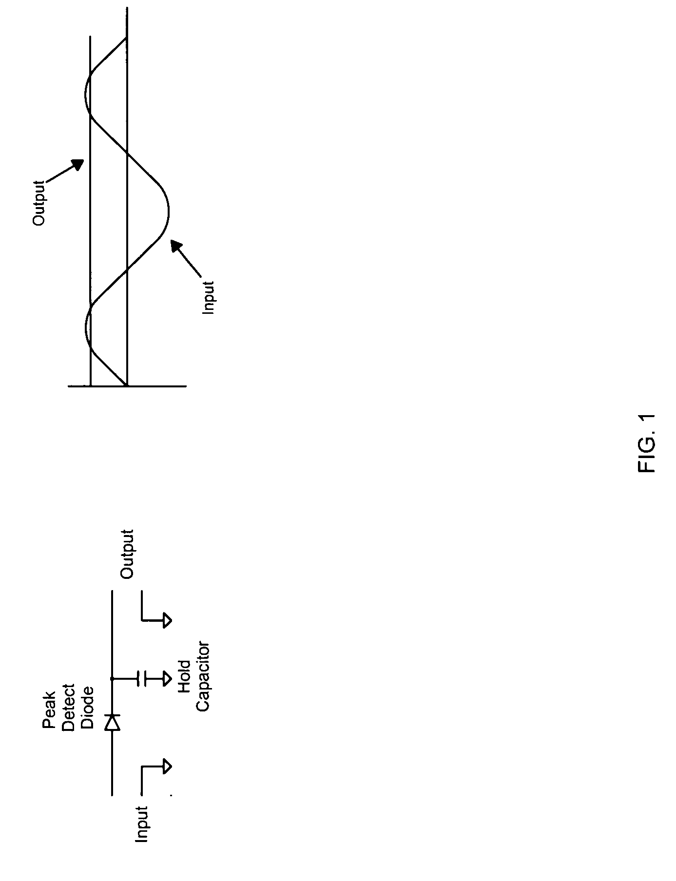
[0011] The reference “Strap Diode” indicates a strap diode. Strap Diode has an input and an output. The reference “Peak Detect Diode” indicates a peak detect diode. Peak Detect Diode has an input and an output. Peak Detect Diode is reverse biased.

[0012] The reference “Feedback Re...


PUM


Abstract

A peak detector circuit for video signals is disclosed. The peak detector circuit comprises a buffer operational amplifier, a strap diode and feedback resistor in order to bootstrap an operational amplifier used in the circuit and to isolate and provide feedback for the circuit An alternative embodiment of this invention utilizes a transistor instead of a strap diode to provide faster charging for a hold capacitor used in the circuit through current gain action of the transistor. The peak detector circuit of this invention permits tracing the input voltage while the operational amplifier remains in the active region, where it is the fastest, without going into saturation during negative cycles of the signal.

Description

BACKGROUND OF THE INVENTION [0001] This invention pertains to a fast peak detector circuit for use in video equipment. Peak detectors are well known to the persons knowledgeable in the pertinent arts as important components in electronic design that can be used to measure amplitude of a signal. Peak detectors are typically used in measuring signal strength or as part of an automatic gain control circuitry. When peak detectors are used in video equipment, speed with which peak detectors react to the input signal is very important because video signals are very fast and the peak portion of the signal may contain very little energy, thus making it difficult to detect and trace. DESCRIPTION OF PRIOR ART [0002] Disadvantages of the peak detectors of the prior art, when used with video signals, will be better understood with reference to FIG. 1 and FIG. 2. FIG. 1 shows a typical peak detector comprising a rectifying element (indicated by “Peak Detect Diode”) and peak hold capacitor (indic...

Claims


Application Information

Patent Timeline
IPC IPC(8): H03K5/153
CPCG01R19/04
Inventor GERSHFELD, JACK
Owner GERSHFELD JACK
Why Eureka
Try Eureka