
Medical waste disposal system assembly

Active Publication Date: 2007-02-01
BIOFLUID TECH
View PDF38 Cites 24 Cited by
  • Summary
  • Abstract
  • Description
  • Claims
  • Application Information

AI Technical Summary

Benefits of technology

[0004] Accordingly, the claimed invention provides an apparatus for containment of biological waste materials with improved storage, handling, disposal and cleaning characteristics. The claimed invention includes an assembly which is seated atop a vessel for biological waste storage. The assembly allows for passage of biological materials into the vessel, and also includes a manual control and closing member to seal the vessel for transportation to a waste disposal station.
[0005] To improve health care worker safety, the assembly guards against unintended waste spillage through the inclusion of a closing member operated by a knob which is automatically locked when turned to the ‘closed’ position. Consequently, the assembly must be manually unlocked in order for the vessel to be emptied of its contents. Quick entry and release grooves incorporated into the top of the assembly allow for sealed connection to a waste disposal device, which can detect closing member pressure and position due to the incorporation of a magnet into the lock release button. Button position can be derived from magnetic or other sensors located on a biofluid disposal station, and are derived by the position of the assembly relative to the disposal device. To improve operator efficiency and versatility of the system a sensor feature is incorporated into the assembly / vessel structure and the wash disposal station. Magnetic or RF signals located on the vessel assembly instruct the disposal station of the appropriate process of data collection.
[0006] Improved handling of biological materials creates additional structural considerations in apparatus design. Health care worker safety is improved by making the assembly shatter resistant as well as leak resistant. Devices for containment of biological materials such as medical waste must withstand a wide range of handling abuses in use and transport and temperatures and pressure ranges since collection and cleansing are likely to occur at substantially different positive and negative atmospheric pressures. Complex organic molecules impact on their surroundings with pH variations, and the assembly must be resistant to chemical degradation from exposure to complex organic molecules. Composition of the assembly and its inner workings must take into account all of these concerns.
[0007] Apparatus component layout also has resulted in operational improvements over previous devices. Connection of the apparatus to a waste removal station is facilitated through quick attachment and release grooves, which provide a sealed discharge path to a mated receiving chamber adapter to safely discharge vessel contents. To improve working efficiency and reliability the apparatus has been designed with a minimum of gaskets and pivot points. The two-point mounting design for the closing member allows for operational simplicity while providing for controlled engagement of the gaskets. Biological material disposal is improved due to the radiused lumen entry port of the closing member which reduces ‘sticktion’ and enables the low torque required for closing member opening and closing. The adjustable closing member seating ring is threaded and allows for compression adjustment of the closing member and gaskets based upon the number of revolutions the closing member seating ring has been inserted into the apparatus housing. The apparatus housing internal chamber has a larger volume and internal dimensions than the apparatus closing member. This expanded chamber coupled with the flattened ball surface to access and direct cleaning fluids to enter the internal chamber of the housing and two-point closing member pivot mounting approach allows for cleaning fluid to access all internal housing and closing member surfaces. As a consequence, apparatus reliability is high and cleaning of apparatus internal components is optimized.
[0008] Finally, medical waste is rarely homogenous, with liquid waste containing solid matter and generating gaseous byproducts. Consequently, the claimed invention provides for enhanced device cleansing through the introduction of a gap between the closing member system and external assembly, allowing for improved automatic cleaning of the assembly after the vessel has been emptied.

Problems solved by technology

Modular medical waste disposal systems help address this need, but can still expose health care workers to risks during disposal of the waste and cleaning of the container.

Method used


Image

  • Medical waste disposal system assembly
  • Medical waste disposal system assembly
  • Medical waste disposal system assembly

Examples


Embodiment Construction

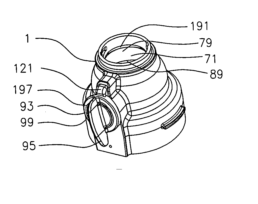
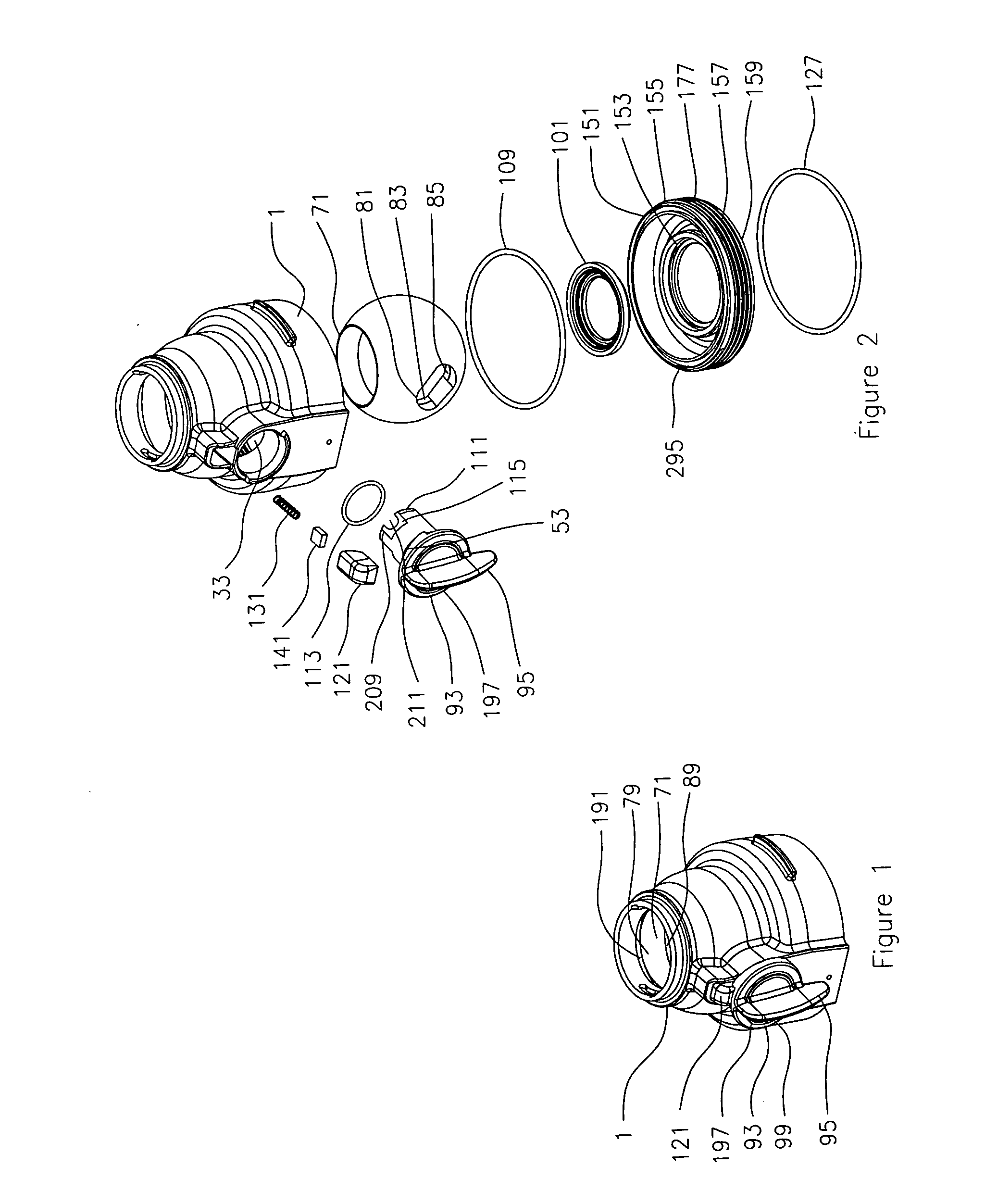
[0023]FIG. 1 is a perspective view of the assembled apparatus. When assembled, housing 1 can be seen with closing member handle 93 and button 121. Since closing member handle is turned to the unlocked and open position, closing member 71 can be seen with angled opening portion 79 of the lumen radiused to facilitate passage of waste (not shown) and subsequent cleaning, straight portion 89 and gap 191 between housing 1 and closing member 71, allowing for greater surface area cleansing of closing member 71 and related parts. The external surface of closing member handle 93 is made up of handle 95 connected to handle face 197 with handle face raised feature 99.

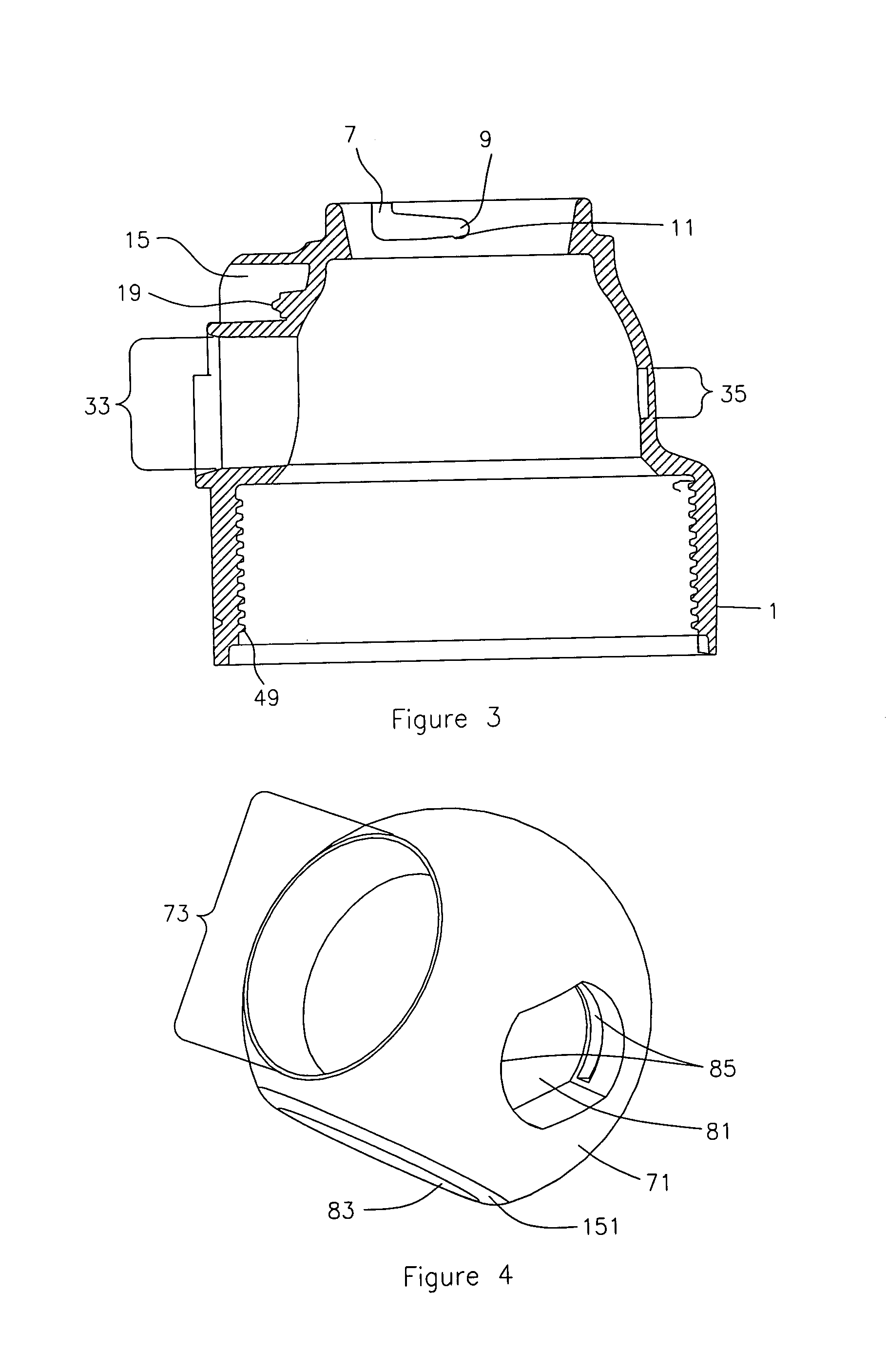
[0024]FIG. 2 is an exploded view of the apparatus and details of the component parts. Starting with the top of the Figure, housing 1 is shown above closing member 71, closing member seal 101 and upper closing member gasket 109, lower closing member gasket 127, all of which seat into closing member seating ring 151. Depicted acros...


PUM


Abstract

A novel collection device for collection, storage and disposal of biological products, in conjunction with an improved cleansing method. Disclosed is an apparatus 301 which includes a locking closing member handle 93 to allow for safe transport and disposal of medical waste. Closing member 71 allows for secure containment of medical waste and subsequent apparatus 301 cleaning. Closing member design includes a gap 191 between closing member 71 and housing 1 which facilitates device cleaning after waste disposal.

Description

TECHNICAL FIELD [0001] The present invention relates to the storage and disposal of biological waste materials. More particularly, the present invention relates to modular containment devices which provide for controlled collection of biological waste materials. Even more particularly, the present invention relates to modular containment devices which guard against undesired spillage while allowing for automated cleaning of the assembly as well as the containment vessel. BACKGROUND ART [0002] Safe and economical handling of medical waste faces a number of hurdles. Devices for containment of medical waste must withstand a wide range of temperatures, pH variations, positive and negative pressure forces, and chemical degradation from exposure to complex organic molecules. Medical waste is rarely homogenous, with liquid waste containing solid matter and generating gaseous byproducts. Secure containment of the same requires addressing all of the above concerns. [0003] Modular medical was...

Claims


Application Information

Patent Timeline
IPC IPC(8): A61M1/00
CPCA61B19/0287F16K5/0668B08B9/28B08B9/00A61B50/36F16K35/027B65D55/14B65D47/30B65D55/02B65D55/10B65D55/022B65D55/12F16K35/16F16K35/022F16K35/025
Inventor RADFORD, RICHARDRADFORD, DREWHOWARD, JACKWILLICH, WAYNE
Owner BIOFLUID TECH
Learn More