
System integration of a steam reformer and gas turbine

a technology of steam reformer and gas turbine, which is applied in the direction of combustible gas production, combustible gas purification/modification, separation processes, etc., can solve the problems of low efficiency, inapplicability of combined-cycle units, and the efficiency of traditional steam power plants generally less than 20%

Inactive Publication Date: 2007-01-18
THERMOCHEM RECOVERY INT
View PDF44 Cites 47 Cited by
  • Summary
  • Abstract
  • Description
  • Claims
  • Application Information

AI Technical Summary

Problems solved by technology

For the small-scale power (10 KWe to 5 MWe ) sector, combined-cycle units are generally not applicable due to low efficiency and high cost.
Such traditional steam power plants are generally less than 20% efficient.
However, many conventional power plants based on biomass combustion have experienced operational difficulties, especially when firing non-wood biomass fuels.
These problems resulted from the deposition of mineral matter on heat exchange surfaces (boiler tubes, superheaters and water walls) or from the agglomeration of ash in the fluidized bed.

Method used


Image

  • System integration of a steam reformer and gas turbine
  • System integration of a steam reformer and gas turbine
  • System integration of a steam reformer and gas turbine

Examples


example 1

[0089] Early system tests were performed using three different biomass feeds: pistachio shells, wood chips, and rice hulls; two different sludge waste products from a recycle paper mill; and a Kraft mill sludge (the two sludge wastes differed primarily in their plastic content); Refuse Derived Fuel (RDF); and dried Municipal Sludge Wastewater (MSW). The waste paper sludge was obtained from a mill located in Northern California. The sludge fraction was composed of short fiber and plastic reject material that is recovered from a clarifier. These sludge wastes were representative of high moisture waste materials that are generated in similar mills located throughout the United States. Table 5 summarizes the operating conditions for the various test runs in the bench-scale unit. Temperatures were varied over the range of approximately 1215° F. to 1450° F. Steam-to-biomass ratios varied from approximately 0.75 to 2.6. Test run durations typically ranged from 4 to 10 hours. No process ope...

example 2

[0091] In another project used to evaluate the low NOx potential of natural gas-fired pulse combustors, burners of the present invention were tested in three different configurations: a pulse burner (0.76 to 5.58 million Btu / hr firing rate range) retrofitted to a Cleaver-Brooks boiler and two versions of a pulse combustor from 2 to 9 million Btu / hr including a 72-tube heater / heat exchanger bundle of the type used in the steam-reforming process. In all the cases, the NOx emissions measured were less than 30 ppm@3% O2. Emissions data from a pilot-scale 72-tube heater / heat exchanger bundle that had already accumulated more than 5,000 hours of operation was measured by several instruments and is presented in Table 7.

TABLE 7EMISSIONS DATA FROM THE 72-TUBE PILOT-SCALE PULSEHEATER TESTSFLUE GASCORRECTEDFLUECORRECTEDFLUE GASCORRECTEDREADINGSAT 3% O2READINGSAT 3% O2READINGSAT 3% O2FIRING RATEO2NOxNOxO2NOxNOxO2NOxNOx(Btu / hr)(%)(ppm)(ppm)(%)(ppm)(ppm)(%)(ppm)(ppm)1.73E+0613.925.113.8615.013....


PUM

PropertyMeasurementUnit
particle sizeaaaaaaaaaa
mean particle sizeaaaaaaaaaa
pressureaaaaaaaaaa

Abstract

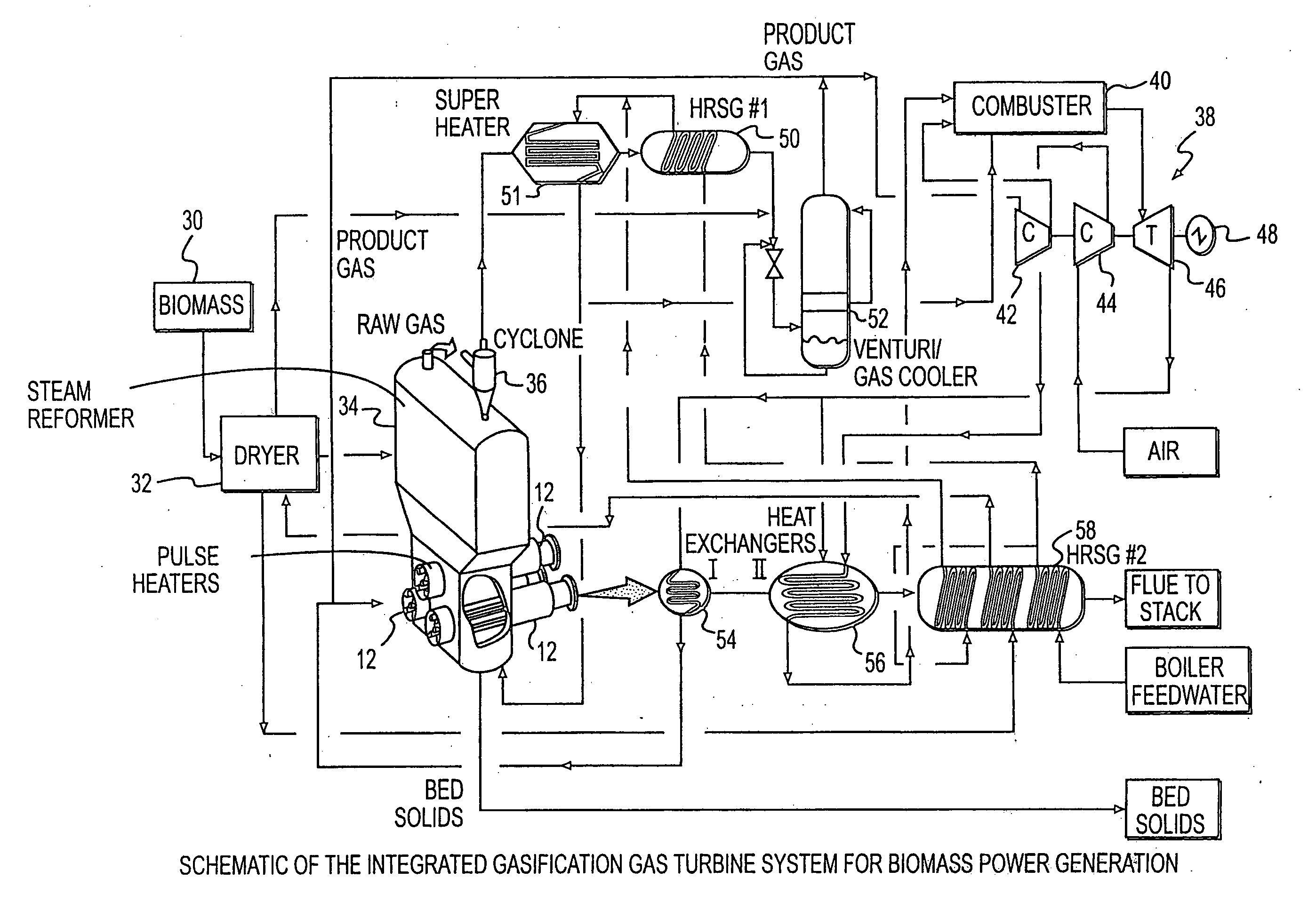
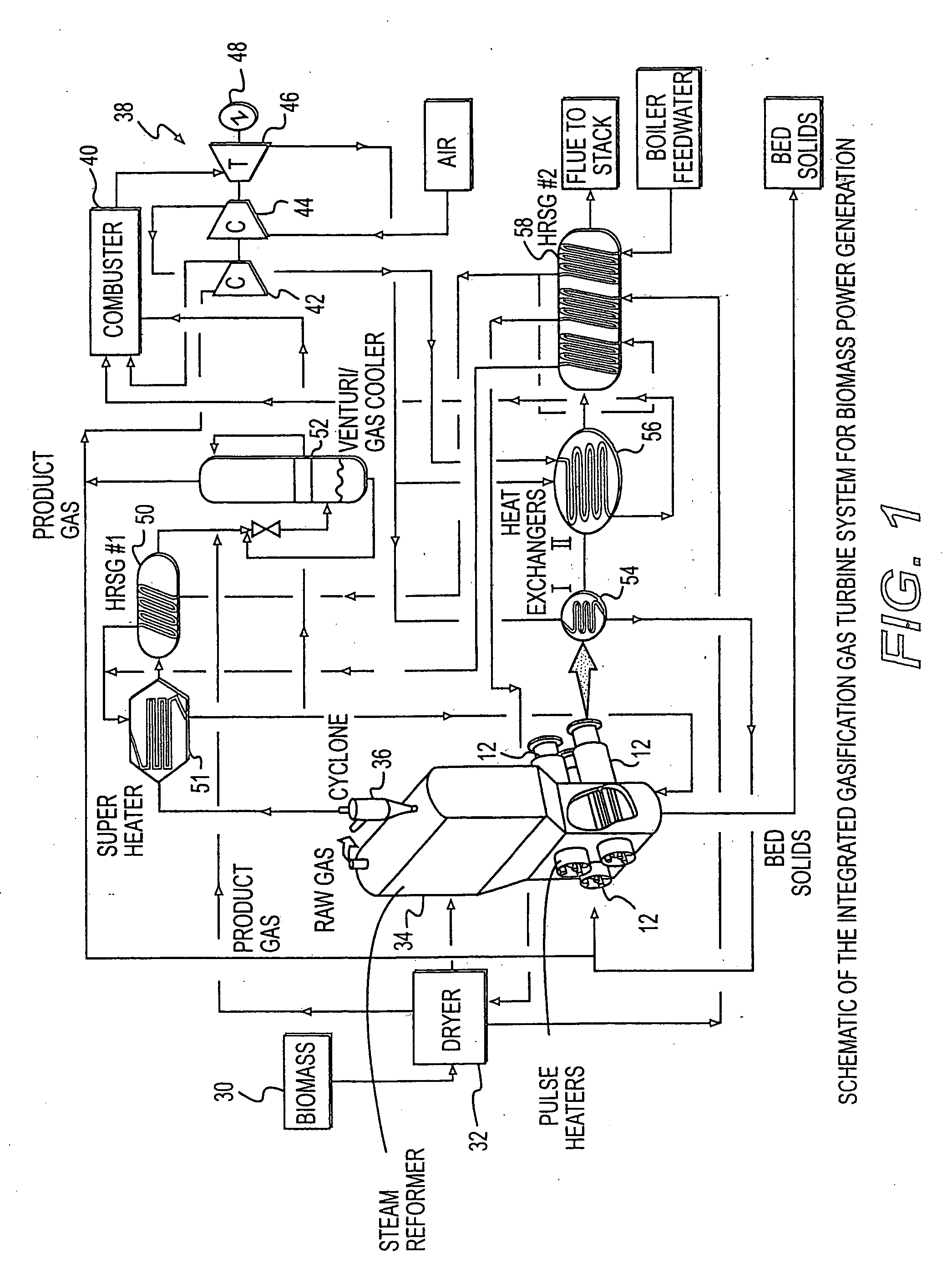
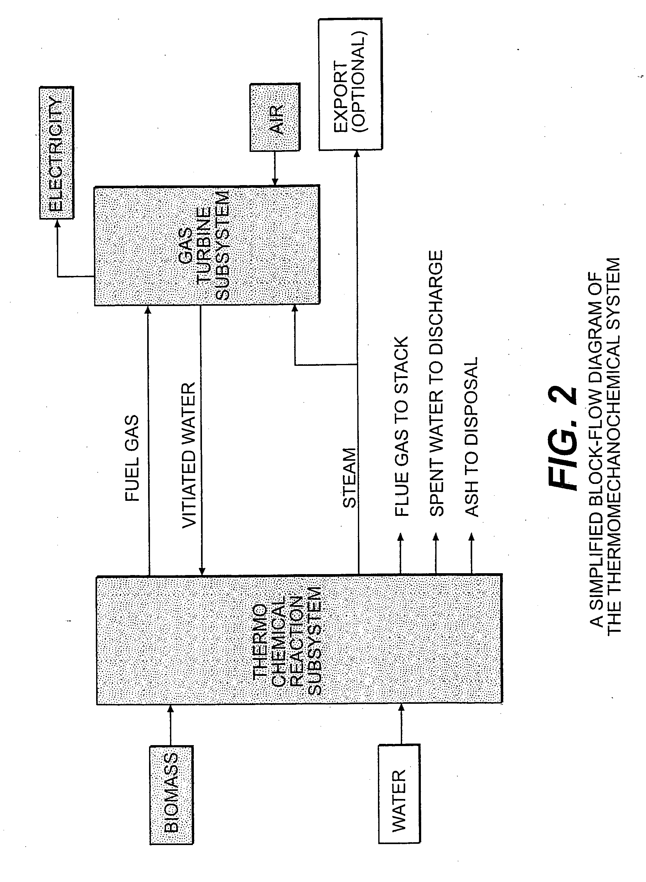
A novel process and apparatus for power generation from biomass and other carbonaceous feedstocks are provided. The process integrates a pulse combustor steam reformer with a gas turbine to generate electricity such that (i) efficiency is higher than those of conventional and current advanced power systems, (ii) emissions are lower than those proposed in the new environmental regulations, and (iii) performance is comparable to that of combined cycle, even though a bottoming cycle is not included here. The pulse combustor steam reformer generates a hydrogen-rich, medium-Btu fuel gas that is fired in a gas turbine to generate electricity. The apparatus may be configured to produce only power or combined heat and power.

Description

RELATED APPLICATIONS [0001] The present application is based upon a provisional application filed on Aug. 19, 1999 having Ser. No. 60 / 149,870.FIELD OF THE INVENTION [0002] The present invention relates to a thermomechanochemical process and apparatus for efficient, clean, modular, cost-effective, green and climate-change neutral power or combined heat and power generation from biomass. Other carbonaceous feedstocks can be used as well. BACKGROUND OF THE INVENTION [0003] Many different options are available for power generation. The fuel can be combusted, gasified, pyrolyzed, bioprocessed or liquefied and utilized in engines, steam power plants (boiler, steam turbine, etc.), gas turbines, gas and steam power plants, and fuel cells. Among these, the most efficient and environmentally superior route for electric power generation is, of course, fuel cells. For the small-scale power (10 KWe to 5 MWe ) sector, combined-cycle units are generally not applicable due to low efficiency and hig...

Claims


Application Information

Patent Timeline
Patent Type & Authority Applications(United States)
IPC IPC(8): F02C3/28C10J3/54
CPCC10J3/482Y02E50/12C10J3/56C10J3/723C10J3/84C10J3/86C10J2300/0909C10J2300/0916C10J2300/0973C10J2300/1261C10J2300/165C10J2300/1671C10J2300/1853C10J2300/1876C10J2300/1884C10J2300/1892C10K1/002C10K1/004C10K1/026C10K1/08C10K1/101C10K1/12F01K23/067F02C3/20F02C3/28Y02E20/18C10J3/54Y02P20/145Y02P20/129Y02E50/10
Inventor CHANDRAN, RAVIMANSOUR, MOMTAZ N.
Owner THERMOCHEM RECOVERY INT
Learn More