
Carry-ripple adder

a technology of carry-ripple adder and adder, which is applied in the field of logic devices, can solve problems such as processing speed, and achieve the effects of reducing the area of the carry-ripple adder, reducing power loss during operation, and small layou

Inactive Publication Date: 2006-12-28
INFINEON TECH AG
View PDF11 Cites 6 Cited by
  • Summary
  • Abstract
  • Description
  • Claims
  • Application Information

AI Technical Summary

Benefits of technology

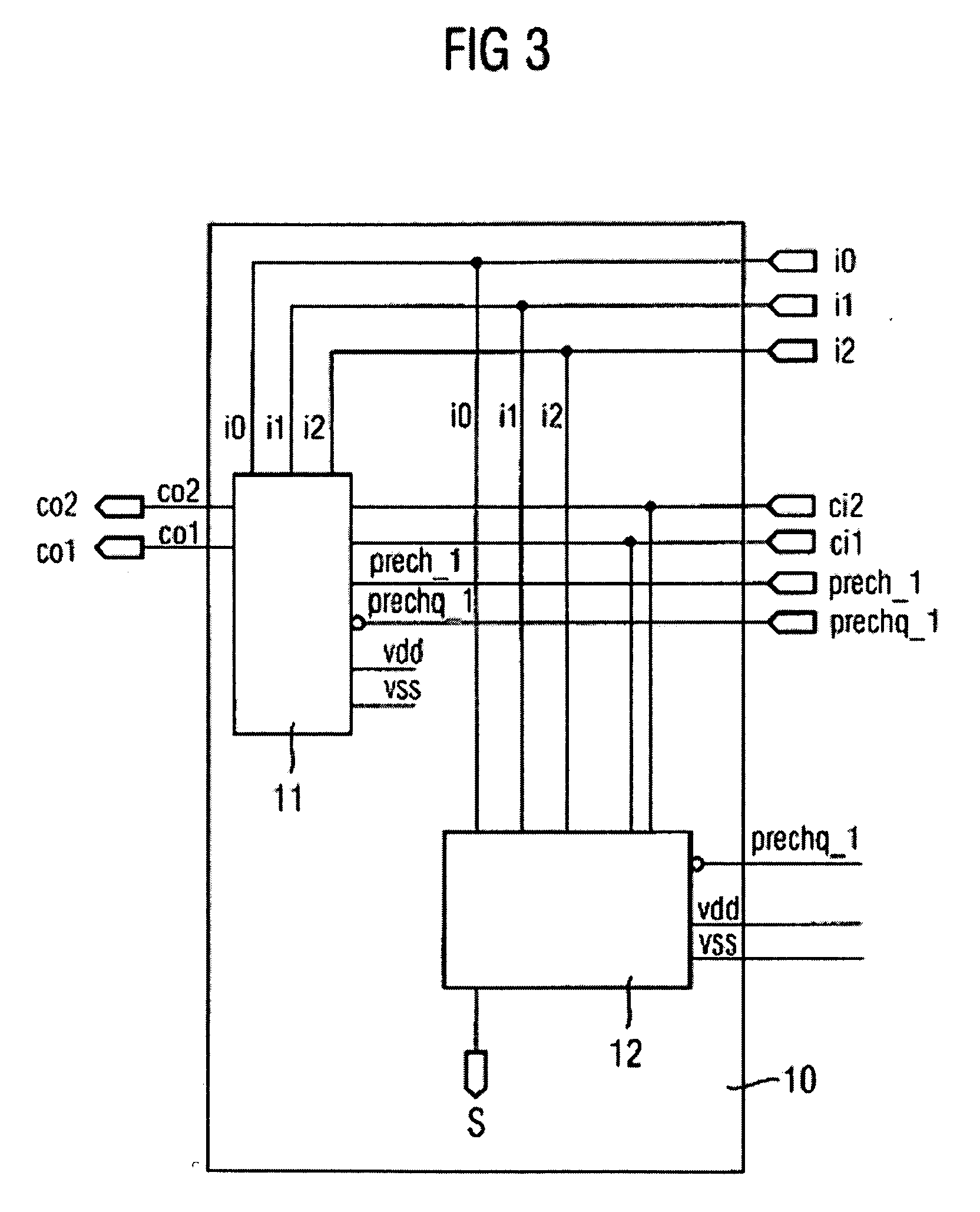
[0009] By way of introduction only, a carry-ripple adders described, including uses thereof. An exemplary carry-ripple adder enables small layouts, or reduction in the area for the carry-ripple adder, and a reduced power loss during operation. A carry-ripple adder may generate two carries, or carry bits, of equal significance, where the carries, or carry bits, are passed directly to the next stage of a multistage carry-ripple adder and assessed therein.
[0010] An exemplary carry-ripple adder may have three first inputs for supplying three input bits of equal significance 2n that are to be summed, two second inputs for supplying two carry bits of equal significance 2n+1 that are also to be summed, one output for outputting a calculated sum bit of significance 2n, and two outputs for outputting two calculated carry bits of equal significance 2n+1 which is higher than the significance 2n of the sum bit. A final carry-ripple stage VMA (vector merging adder) may be used even after a reduction to three bits. This makes it possible to save on one carry save stage, which has an advantageous effect on the processing speed and the substrate area of the overall circuit, or to use the third input bit of each carry-ripple adder for the efficient implementation of accumulators, for example in MAC structures.
[0011] Dynamic implementation of carry paths and their logic implementation within a carry-ripple adder additionally make it possible to optimize the area and speed in comparison with complementary or differential CMOS solutions. Simultaneously generating two carries, or carry bits, of equal significance that are assessed in each stage of the carry-ripple adder means that the circuit complexity and the internal wiring complexity are lower than multistage complementary CMOS solutions which are, for example, composed of 3-bit carry save adders and 2-bit carry-ripple adders. This also applies to dynamic carry-ripple adders having three inputs.

Problems solved by technology

However, these configurations are disadvantageous, both as regards the processing speed and as regards the substrate area required, for an implementation using complementary CMOS gates on account of the resultant high number of transistors.

Method used


Image

  • Carry-ripple adder
  • Carry-ripple adder
  • Carry-ripple adder

Examples


Embodiment Construction

[0026] Exemplary carry-ripple adders will now be described more fully with reference to the accompanying drawings. In each of the following figures, components, features and integral parts that correspond to one another each have the same reference number. The drawings of the figures are not true to scale.

[0027]FIG. 1 shows a schematic illustration of a 3 & 2 to 3 carry-ripple adder 10 having three bit inputs i0, i1 and i2, two equivalent carry inputs ci1, ci2, two equivalent carry outputs co1, co2 and a sum output s.

[0028]FIG. 2 shows a truth, or function, table for one bit in the carry-ripple adder shown in FIG. 1. On the basis of the coding selected for the two equivalent carry output signals co2 and co1, input combinations where ci2=1 and ci1=0 (hashed in FIG. 2) do not occur during operation since ci2 can only be set if ci1 has also been set, from which a double carry is deduced. This fact that “don't care elements” occur is used to minimize the circuit. The simple sum of the...


PUM


Abstract

A carry-ripple adder having inputs for supplying three input bits of equal significance 2n that are to be summed and two carry bits of equal significance 2n+1 that are also to be summed. A calculated sum bit of significance 2n and two calculated carry bits of equal significance 2n+1 which are higher than the significance 2n of the sum bit are provided at outputs. A final carry-ripple stage VMA may be used even after a reduction to three bits.

Description

PRIORITY AND CROSS REFERENCE TO RELATED APPLICATION [0001] This application is a continuation of International Application No. PCT / DE2004 / 000796 filed Jan. 29, 2004, which claims priority to German application 103 05 849.4 filed Feb. 12, 2003, both of which are incorporated herein in their entirety by reference. BACKGROUND [0002] 1. Field of the Invention [0003] The present invention relates to the field of logic devices, and more particularly, it relates to 3 & 2 to 3 carry-ripple adders. [0004] 2. Description of the Related Art [0005] Carry-ripple adders have sequential carry logic, and similar carry-save adders, they have a plurality of inputs of equal significance and, during operation, sum the bits applied to these inputs. The sum is provided at outputs of different significance, for example in binary coded numerical notation (BCD). [0006] In order to add a plurality of bits of equal significance, for example in multipliers, it is known to build carry save adder arrays, for exa...

Claims


Application Information

Patent Timeline
IPC IPC(8): G06F7/50G06F7/509G06F7/53G06F7/60H04B
CPCG06F7/509G06F2207/3872G06F7/607G06F7/5318
Inventor BERNHARDT, MARCHATSCH, JOELKAMP, WINFRIEDKOEPPE, SIEGMAR
Owner INFINEON TECH AG
Learn More