
Tissue repair device and fabrication thereof

Inactive Publication Date: 2006-12-28
ETHICON INC
View PDF15 Cites 4 Cited by
  • Summary
  • Abstract
  • Description
  • Claims
  • Application Information

AI Technical Summary

Benefits of technology

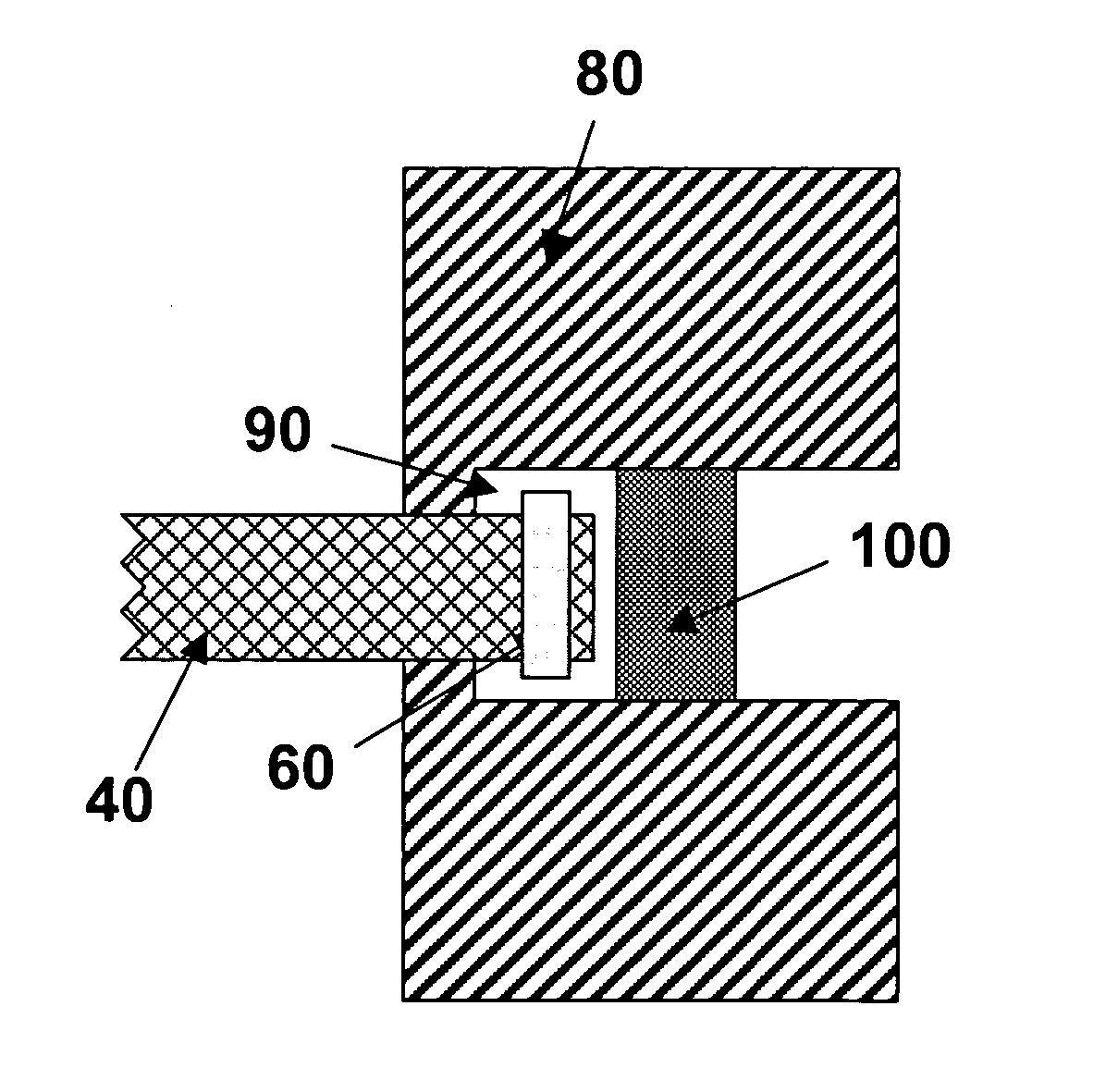
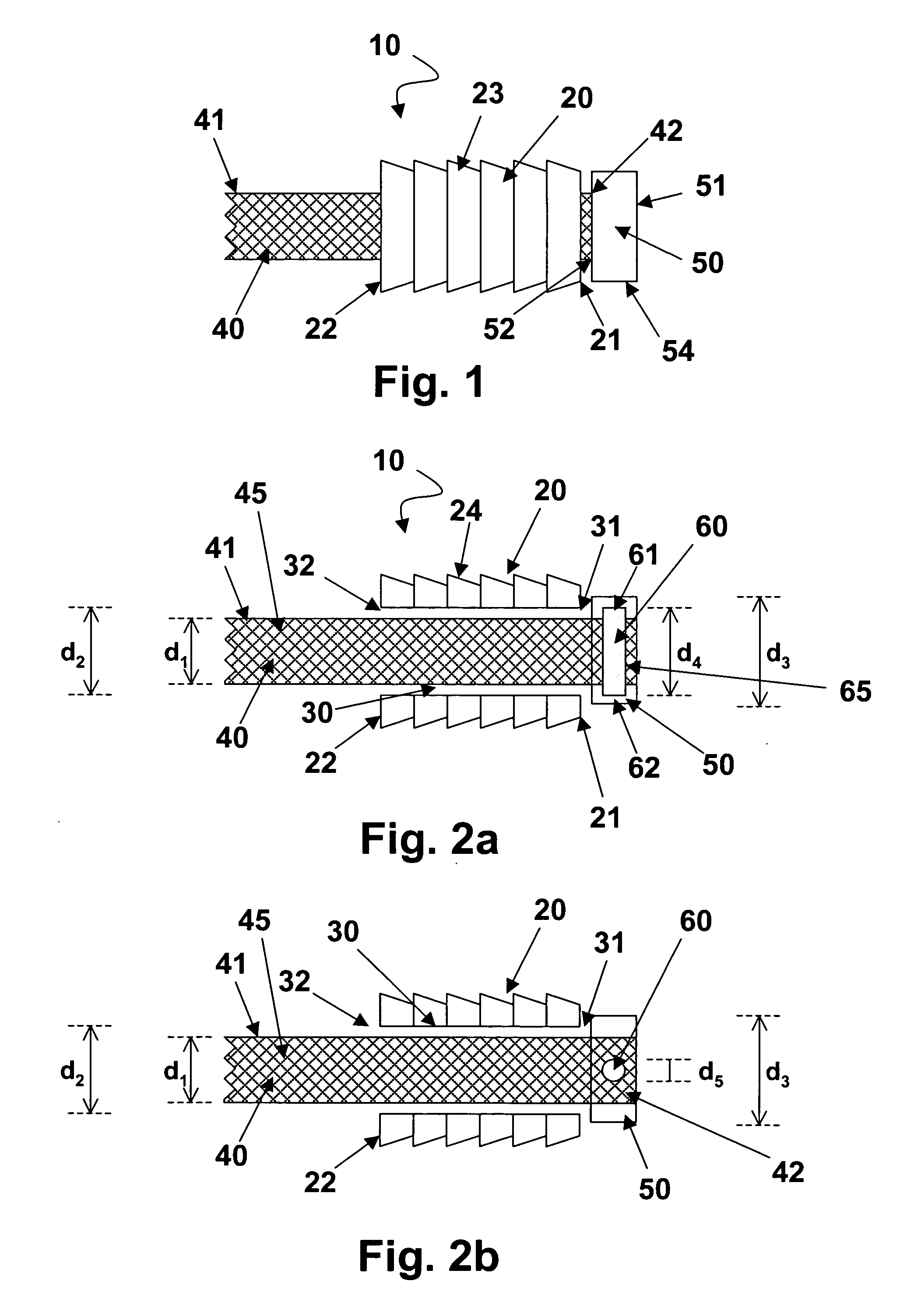
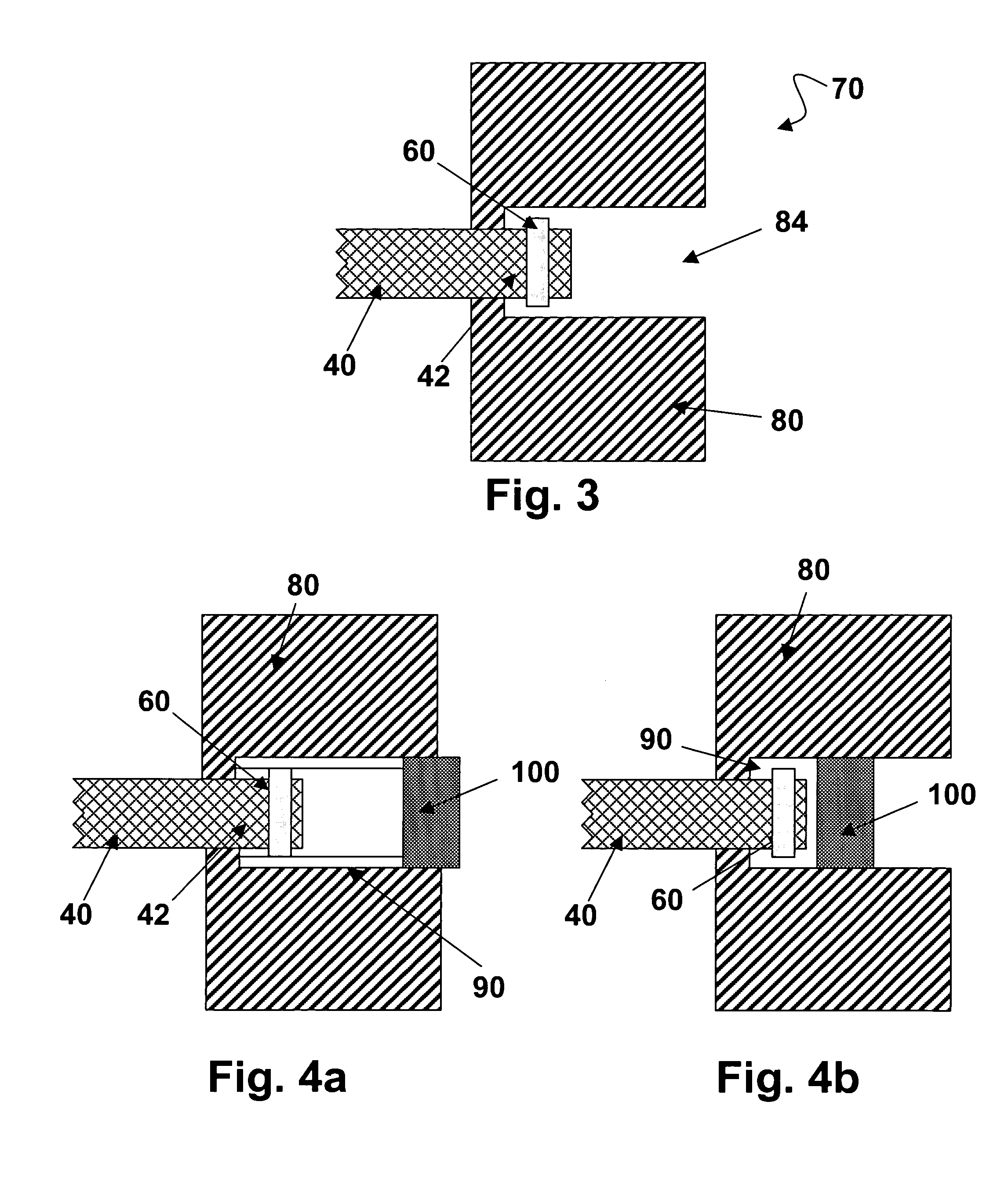
[0005] The tissue repair device of the present invention overcomes the above stated limitations by providing a device having a cannulated anchor member, a cord that passes through the anchor cannulation, a rod member, and a stopper to prevent the cord from passing back through the anchor cannulation, wherein the rod member is passed through and end of the cord and imbedded within the stopper. The stopper member is molded about the cord end containing the rod member. This enhances the attachment strength of the cord to the stopper.
[0008] The novel tissue repair devices having cannulated anchor members, cords and stopper members overcome the disadvantages of the prior art by providing secure fixation and minimizing or eliminating the possibility of the cord separating from the anchor member.

Problems solved by technology

Although generally satisfactory for their intended purpose, there may be certain disadvantages attendant with the use of such attachment methods.
For example, a disadvantage of the insert molding method may be low pull-out strength of the cord from the anchoring component.
This is believed to be caused by the difficulty in general, conventional compression molding processes to form a secure attachment between the cord and anchoring components.
When using an eyelet or small hole, the hole or the eyelet are related to the removal or absence of material from the anchoring component which may, in some cases, result in mechanical strength lost, or it may be difficult or not possible to place a hole or an eyelet in or on the anchoring component due to a low profile configuration or limited space.

Method used


Image

  • Tissue repair device and fabrication thereof
  • Tissue repair device and fabrication thereof
  • Tissue repair device and fabrication thereof

Examples


example 1

Forming Rod / Cord / Stopper Assemblies

[0045] In this example, a general compression molding process was used to form rod 60 / cord 40 / stopper 50 assembly.

[0046] The rod 60 was formed by extruding 95 / 5 poly(lactide-co-glycolide) (95 / 5 PLGA) from PURAC (Gorinchem, The Netherlands), with an Inherent Viscosity (I.V) of 2.33 dl / gm (measured in chloroform at 25° C. and a concentration of 0.1 gm / dl) at 200° C. in a DACA Spinline extrusion system. The diameter of rod 60 was 0.635 millimeter. Rod 60 was cut to 0.4 centimeters in length.

[0047] The material used to form stopper 50 was 95 / 5 poly(epsilon-caprolactone-co-p-dioxanone) with an Inherent Viscosity (I.V) of 1.5 dl / gm (measured in chloroform at 25° C. and a concentration of 0.1 gm / dl). The 95 / 5 poly(epsilon-caprolactone-co-p-dioxanone) was prefabricated into a short tube with dimensions of: OD 0.38 centimeters, ID 0.23 centimeters, and 0.30 centimeters long (by extrusion under an extrusion temperature of 85° C.).

[0048] The cord was a th...

example 2

Surgical Procedure

[0053] A patient is prepared for spinal fusion surgery in a conventional manner. The surgery will fuse one or more levels of the spinal column. The patient is anesthetized in a conventional manner. The tissue repair site is accessed by making an incision through the abdominal cavity and dissecting down to the spinal column. A sterile device of the present invention is prepared for implantation into the patient, the device having anchor members mounted to each end of the cord. The operative site is prepared to receive the anchor members of the repair device by dissecting through the ligamentous structure attached to the vertebral bodies of the spinal column that will be fused. A discectomy procedure is performed to remove the disc of the vertebral level to be fused and a bone graft is inserted into the discs space. A hole is drilled into the vertebral body above and below the disc space. The anchor bodies are then inserted into drilled holes in the adjoining verteb...


PUM

PropertyMeasurementUnit
Molar ratioaaaaaaaaaa
Biocompatibilityaaaaaaaaaa

Abstract

A device for use in tissue repair, a method of using the device in a surgical procedure and a method of making the device. The device is an assembly of a cannulated anchor with a cord passed through it, and a stopper to prevent the cord from passing back through the anchor.

Description

FIELD OF THE INVENTION [0001] The present invention relates to medical devices. More specifically medical devices for use in tissue repair, surgical procedures for repairing tissue using such devices, and a method of making the devices. BACKGROUND OF THE INVENTION [0002] There are many applications in the field of orthopaedics for medical devices used in surgical procedures, wherein there is a requirement to anchor at least a section of a cord (e.g., a tape or a surgical suture) within a bone bore hole. A solid and secure attachment between the cord and anchoring components of anchor devices is essential to the success of the device. Such conventional devices include vertebral straps, suture anchors, and suture staples. [0003] Conventionally known methods for attaching or securing cords to anchoring components include insert molding, passing the cords through eyelets or small holes in the anchoring components, compressing the cord between surfaces of the device, etc. Although genera...

Claims


Application Information

Patent Timeline
IPC IPC(8): B29C45/14
CPCA61B17/0401A61B2017/044A61B2017/0458B29L2031/753B29C2043/181B29K2105/258B29K2995/0056B29C43/18
Inventor LI, ZHIGANGCOOPER, KEVINSHISSIAS, RAYMOND S.ZHANG, QIANG
Owner ETHICON INC
Learn More