
Composite guide vane

Active Publication Date: 2014-10-02
GKN AEROSPACE SWEDEN AB
View PDF2 Cites 3 Cited by
  • Summary
  • Abstract
  • Description
  • Claims
  • Application Information

AI Technical Summary

Benefits of technology

The patent text describes a guide vane that has a strengthened attachment to a housing and a reduced thickness at the location where it is attached. This may be achieved by delimiting the first opening of the guide vane with a cover portion. The technical effect of this design is an improved strength and efficiency of the guide vane.

Problems solved by technology

However, the '490 solution implies that the corners of the composite vane may be subjected to large stresses.
However, it is generally not desired to put the opening or openings too far from the leading edge and trailing edge, respectively, since this may result in an attachment of the guide vane to the first housing which does not provide a sufficient stiffness.
Moreover, since the widening of the first attachment portion occurs over 15% or less of the guide vane length, the widening will not, at least not to any greater extent, have a negative influence on the aerodynamic properties and / or the weight of the guide vane.

Method used


Image

  • Composite guide vane
  • Composite guide vane
  • Composite guide vane

Examples


Embodiment Construction

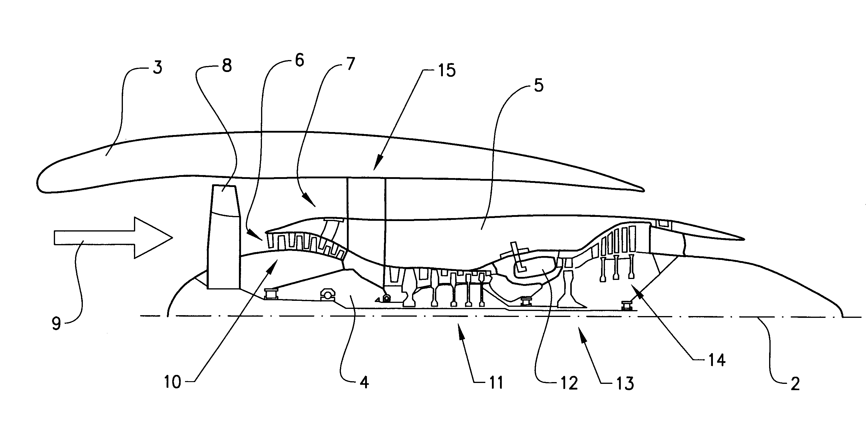
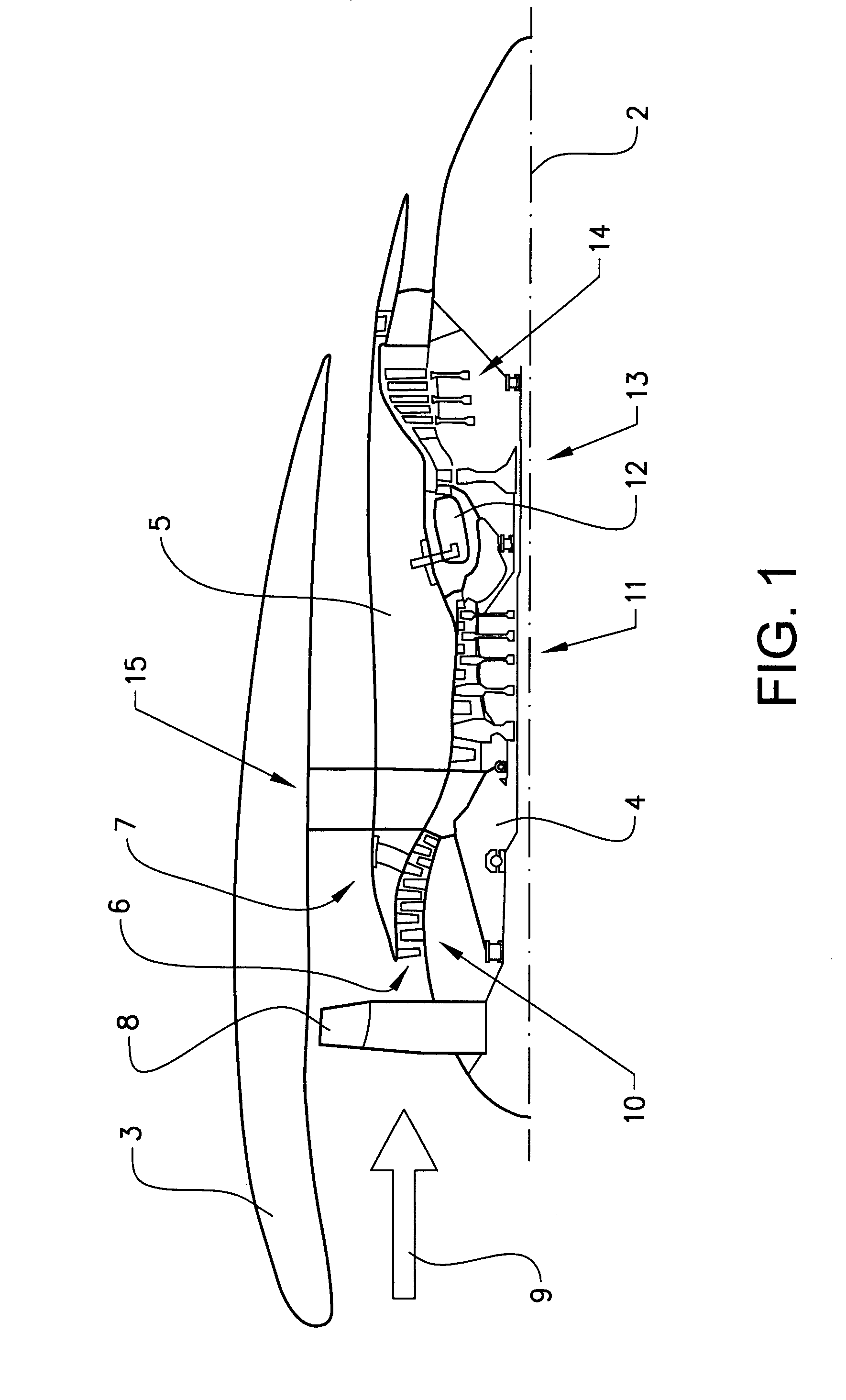
[0046]The invention will below be described for a turbofan gas turbine aircraft engine 1, which in FIG. 1 is circumscribed about an engine longitudinal central axis 2. The engine 1 comprises an outer casing or nacelle 3, an inner casing 4 (rotor) and an intermediate casing 5 which is concentric to the first two casings and divides the gap between them into an inner primary gas channel 6 for the compression of air and a secondary channel 7 in which the engine bypass air flows. Thus, each of the gas channels 6, 7 is annular in a cross section perpendicular to the engine longitudinal central axis 2.

[0047]The engine 1 comprises a fan 8 which receives ambient air 9, a booster or low pressure compressor (LPC) 10 and a high pressure compressor (HPC) 11 arranged in the primary gas channel 6, a combustor 12 which mixes fuel with the air pressurized by the high pressure compressor 11 for generating combustion gases which flow downstream through a high pressure turbine (HPT) 13 and a low press...


PUM


Abstract

A composite guide vane for a gas turbine structure is adapted to extend in a guide vane direction from a first housing towards a second housing of the gas turbine structure. The guide vane includes a guide vane length in the guide vane direction and the guide vane includes a first attachment portion with at least one first opening for attachment of the guide vane to the first housing. The first opening extends in a first opening direction which forms an angle with the guide vane direction. The guide vane includes a cover portion including a first material and a core portion which is at least partially enclosed by the cover portion.

Description

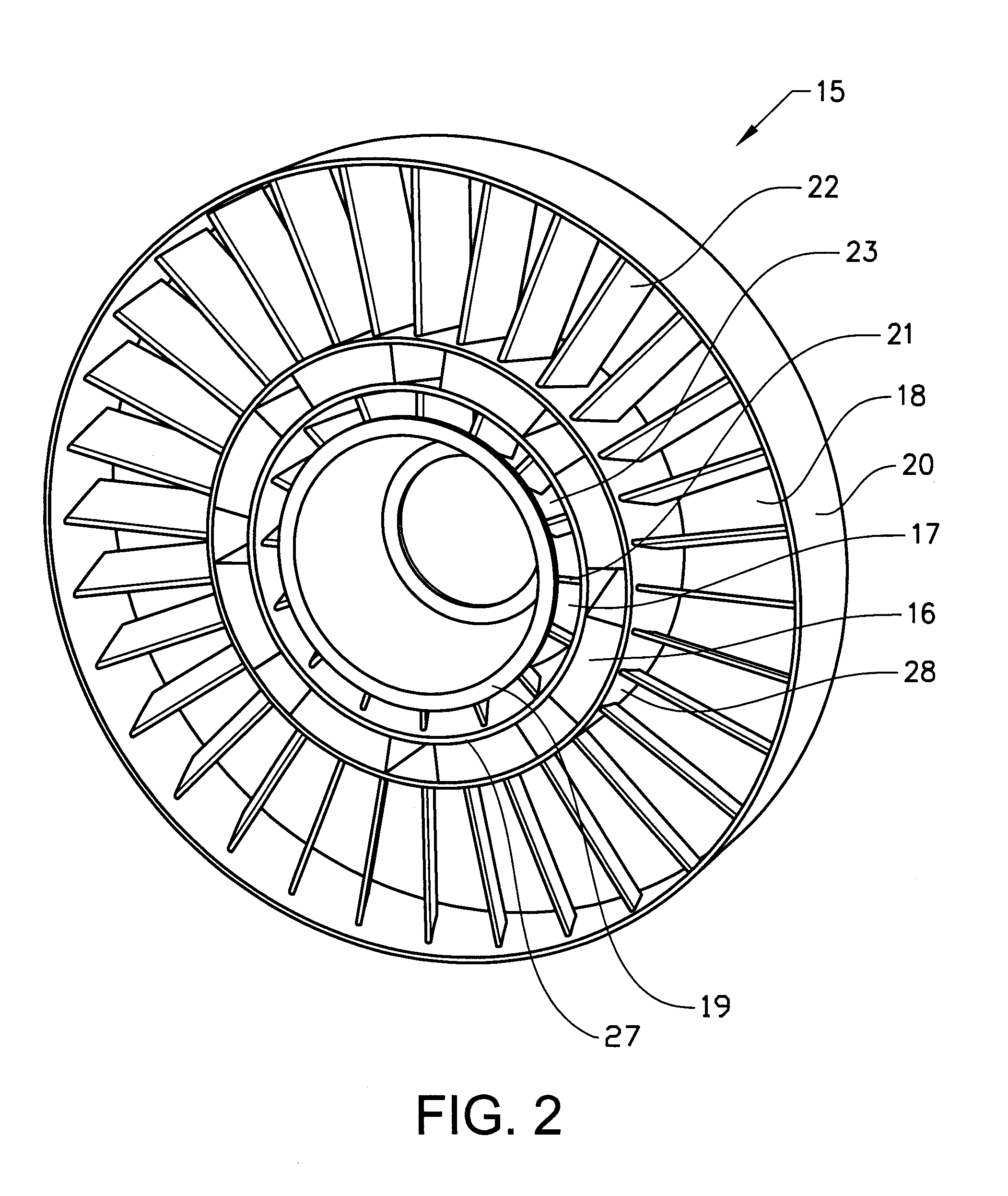
BACKGROUND AND SUMMARY[0001]The present disclosure relates to a composite guide vane. Further, the present disclosure relates to a gas turbine structure. Moreover, the present disclosure relates to a gas turbine engine. Furthermore, the present disclosure relates to an aeroplane.[0002]A gas turbine engine may be used as a jet engine. The term jet engine includes various types of engines, which admit air at relatively low velocity, heat it by combustion and shoot it out at a much higher velocity.[0003]Accommodated within the term jet engine are, for example, turbojet engines and turbo-fan engines. The invention will below be described for a turbo-fan engine, but may of course also be used for other engine types.[0004]A gas turbine structure, which may sometimes be denoted a case or frame, is used for supporting and carrying bearings, which in turn, rotatably support rotors. Conventional turbo fan engines have a fan frame, a mid-frame and an aft turbine frame. These frames constitute ...

Claims


Application Information

Patent Timeline
IPC IPC(8): F01D9/02
CPCF01D9/02F01D9/04F01D25/246F01D25/28F05B2260/301Y02T50/60
Inventor JANSSON, NIKLASREIMERS, ROBERT
Owner GKN AEROSPACE SWEDEN AB
Learn More