
Vehicle seat

Active Publication Date: 2017-12-28
TS TECH CO LTD +1
View PDF2 Cites 2 Cited by
  • Summary
  • Abstract
  • Description
  • Claims
  • Application Information

AI Technical Summary

Benefits of technology

This patent describes a vehicle seat with a unique design that improves the comfort and flexibility of the seat for the occupant. The seat does not require a lateral pipe, which means the occupant does not feel uncomfortable bumps or contact. The seat back frame is made up of fewer parts, reducing assembly and weight. The thickness of the pad material between the occupant and the seat belt retractor can be increased for better comfort. The attachment strength of the seat belt retractor can also be improved. The seat back frame has a unique design with multiple pipes that further reduces the number of parts and increases stiffness. The manufacturing process is also low-cost. Overall, this design improves the overall comfort and flexibility of the vehicle seat.

Problems solved by technology

However, according to the conventional configuration of the vehicle seat, an occupant seated on the vehicle seat may experience an uncomfortable contact feeling due to the presence of the lateral pipe of the seat back frame, and the occupant's seating feeling may be impaired.
Further, the seat back frame includes a large number of constituent parts, which disadvantageously leads to an increase in workload for assembly of the seat back frame and an increase in weight of the seat back frame.

Method used


Image

  • Vehicle seat
  • Vehicle seat
  • Vehicle seat

Examples


first embodiment

[0030]The first embodiment of the present invention will be described in detail with reference to the appended drawings.

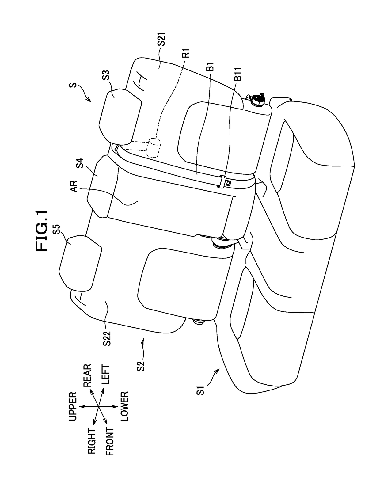
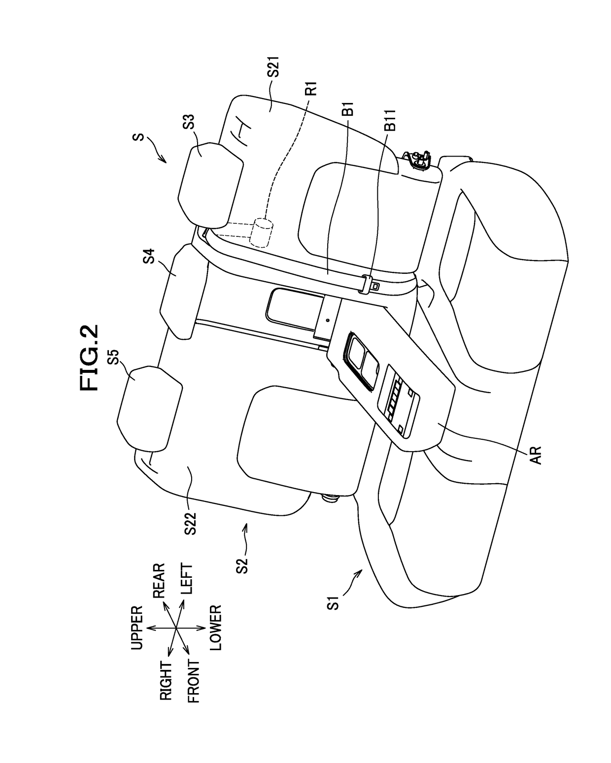
[0031]As seen in FIG. 1, a vehicle seat according to this embodiment is configured as a car seat S installed in an automobile. The car seat S mainly includes a seat cushion S1, a seat back S2, headrests S3, S4, S5, a seat belt B1 for a center seat, a seat belt retractor R1 configured to retract the seat belt B1, and an armrest AR.

[0032]The armrest AR is supported by the seat back S2 and rotatable frontward and rearward with respect to the seat back S2 between a use position as shown in FIG. 2 in which position the armrest AR is to be used and a stowed position as shown in FIG. 1 in which position the armrest AR is retracted into the seat back S2. The armrest AR includes a frame (not shown), and the frame is upholstered with a pad material made of a cushion material such as urethane foam, and an outer skin material made of fabric or the like. In the following descri...

second embodiment

[0075]The second embodiment of the present invention will be described below. In this embodiment, parts different from those described in the first embodiment will be described in detail, and parts similar to those previously described in the first embodiment will be denoted by the same reference numerals and detailed description thereof will be omitted.

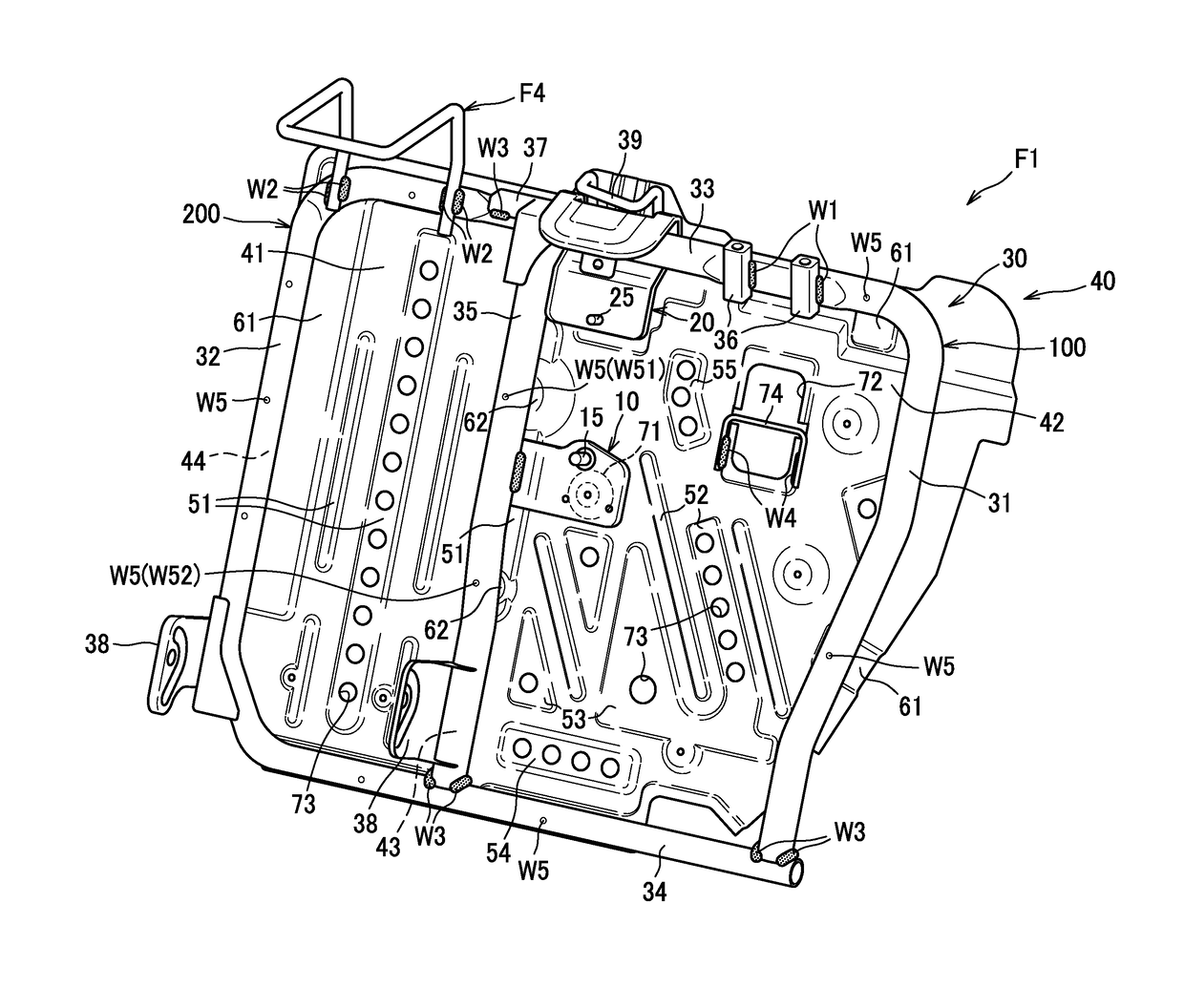
[0076]As seen in FIG. 9, the seat back frame F2 that constitutes a framework for the first seat back S21 mainly includes a pipe frame 30, a back panel 40 and a wire member 50.

[0077]As seen in FIG. 10, the pipe frame 30 includes a third pipe member 300, a fourth pipe member 400 and a fifth pipe member 500.

[0078]The third pipe member 300 is formed by bending a metallic pipe member into a substantially U-shaped configuration, and includes left and right longitudinal pipe portions 310, 320 and a lateral pipe portion 330 connecting upper end portions of the longitudinal pipe portions 310, 320. The third pipe member 300 is made of a pipe m...


PUM


Abstract

A vehicle seat including a seat cushion, a seat back, a seat belt, and a seat belt retractor is provided. The vehicle seat includes: a seat back frame comprising: right and left side frames disposed at a distance away from each other in a lateral direction; an upper frame connecting upper end portions of the right side frame and the left side frame; a lower frame connecting lower end portions of the right side frame and the left side frame; and a connecting frame made of a pipe member and disposed at distances away from the right and left side frames and connecting the upper frame and the lower frame; and a first bracket by which the seat belt retractor is attached to the seat back frame. The first bracket is provided on the connecting frame at distances away from the upper frame and the lower frame.

Description

CROSS REFERENCE TO RELATED APPLICATIONS[0001]The present application claims priority from Japanese Patent Application No. 2016-125330 filed on Jun. 24, 2016, the disclosure of which is incorporated herein by reference in its entirety.TECHNICAL FIELD[0002]The present invention relates to a vehicle seat comprising a seat cushion, a seat back, a seat belt, and a seat belt retractor configured to retract the seat belt.BACKGROUND ART[0003]As a conventional configuration of a seat back frame for an automobile rear seat, JP 2003-009985 A discloses a seat frame, which comprises a U-shaped main frame, a lower frame connecting lower portions of the main frame, a longitudinal pipe extending between an upper portion of the main frame and the lower frame to bridge a gap therebetween, and a lateral pipe extending between one of right and left frames constituting the main frame and the longitudinal pipe to bride a gap therebetween. In a vehicle seat including such a seat back frame, a seat belt re...

Claims


Application Information

Patent Timeline
IPC IPC(8): B60N2/68
CPCB60N2/682B60N2/686B60N2/688B60N2/803B60N2/894B60N2/897B60R22/26
Inventor YONEHARA, HIDETAKAMIYAWAKI, KAZUYANOMURA, HIROYUKIOKIMURA, ATSUSHIIKEDA, HIROKIMIZUKOSHI, TOSHIMITSUOGA, YUMA
Owner TS TECH CO LTD
Learn More