
Diode-pumped, solid-state laser with chip-shaped laser medium and heat sink

a solid-state laser and laser medium technology, applied in the direction of laser cooling arrangements, laser details, active medium materials, etc., can solve the problems of severe thermal distortion in the region, and poor mode matching and pumping efficiency of side pumping and end pumping. , to achieve the effect of improving mode matching, adequate pumping coupling efficiency, and improving mode matching

Inactive Publication Date: 2006-12-21
ELECTRO SCI IND INC
View PDF14 Cites 7 Cited by
  • Summary
  • Abstract
  • Description
  • Claims
  • Application Information

AI Technical Summary

Benefits of technology

[0008] To improve mode matching between the pumping energy and lasing mode volume in side-pumped solid-state laser designs, skilled persons may find it desirable to make the solid-state laser medium thin. However, rod-shaped lasing media, for example, become mechanically fragile when the rod becomes too thin, so it becomes difficult to make good thermal contact between the rod and a heat sink without damaging the rod.
[0009] In some embodiments, a chip-shaped lasing medium can be face pumped to improve mode matching between the pumping energy and lasing mode volume. The chip thickness and laser medium doping level can be designed and controlled to ensure adequate pumping coupling efficiency. The chip shape can also be employed to provide greater surface areas for cooling the laser medium. The laser pumping package and the chip-shaped design can be scalable to offer higher pumping power and high output power. In some exemplary scalable laser embodiments, a plurality of laser pumping packages can be employed to pump a single laser medium. In other exemplary scalable laser embodiments, multiple laser media are each pumped by a single laser pumping package. In yet other exemplary scalable laser embodiments, a single diode laser bar or array can be employed to pump a plurality of laser media. Different orientations of the laser pumping packages with respect to the mode volume of one or more laser media can be used to provide better lasing mode quality.

Problems solved by technology

However, since the pumping energy is concentrated into a small area, there is often severe thermal distortion in that region.
Accordingly, end-pumping applications for higher laser power are somewhat limited.
Nevertheless, conventional diode pumping designs have pursued the coupling efficiency at the expense of other considerations due to the high cost of the diode laser power.
However, the mode matching and pumping efficiency for side pumping tend to be poorer than for end pumping.
However, rod-shaped lasing media, for example, become mechanically fragile when the rod becomes too thin, so it becomes difficult to make good thermal contact between the rod and a heat sink without damaging the rod.

Method used


Image

  • Diode-pumped, solid-state laser with chip-shaped laser medium and heat sink
  • Diode-pumped, solid-state laser with chip-shaped laser medium and heat sink
  • Diode-pumped, solid-state laser with chip-shaped laser medium and heat sink

Examples


Embodiment Construction

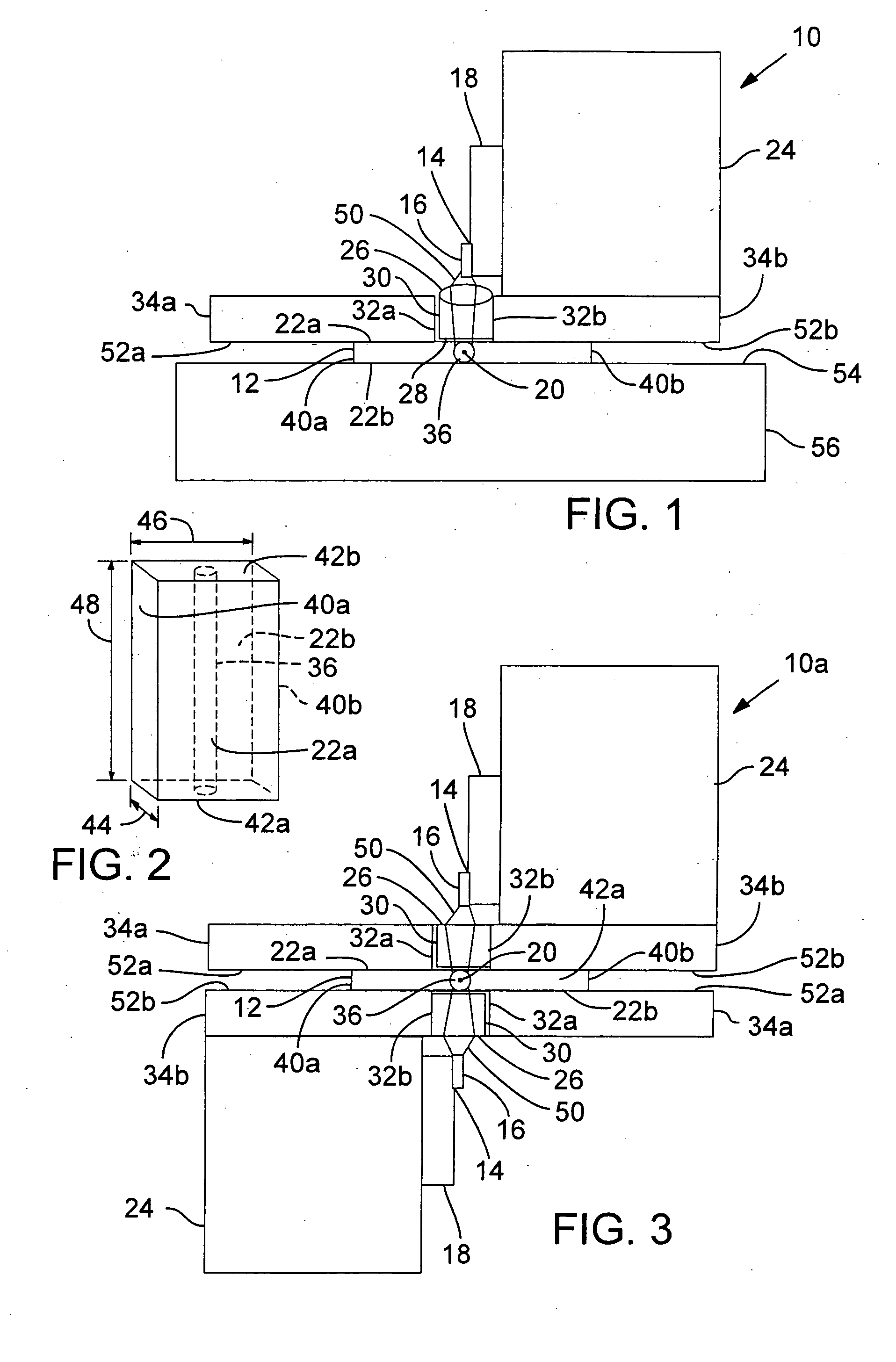
[0023]FIG. 1 shows a cross-sectional view of an exemplary solid-state laser 10 having a chip-shaped laser medium 12. A pumping source, such as one or more diode laser bars or arrays 16, with its heat sink 18 is positioned to pump with its pumping beam 50 the laser medium 12 on its chip face 22. The pumping source has a long dimension or length 38 (FIG. 4) that is generally aligned to be coplanar with or parallel to a lasing axis 20 of the laser medium 12. The direction of the pumping beam 50 is transverse, and preferably perpendicular, to the lasing axis 20 as well as transverse, and preferably perpendicular, to at least one of two large chip faces 22a or 22b (generically, large chip face 22).

[0024] The diode laser package 14, comprising the diode laser bar 16 and the heat sink 18, is preferably positioned against or connected to a temperature controlled heat sink 24 to maintain the diode laser bar 16 at a predetermined temperature. The diode laser bar 16 may include a single bar, ...


PUM


Abstract

A chip-shaped laser medium (12) is side pumped to improve mode matching between the pumping energy (50) and lasing mode volume (36). The chip thickness (44) and laser medium doping level can be designed and controlled to ensure adequate pumping coupling efficiency. The chip shape can also be employed to provide greater chip surface areas (22) for cooling the laser medium (12). The laser pumping package (70), gain module (101), and chip-shaped design can be scalable to offer higher pumping power and high output power. Different orientations of the gain modules (101) with respect to each other can be used to provide better lasing mode quality.

Description

COPYRIGHT NOTICE [0001]© 2005 Electro Scientific Industries, Inc. A portion of the disclosure of this patent document contains material that is subject to copyright protection. The copyright owner has no objection to the facsimile reproduction by anyone of the patent document or the patent disclosure, as it appears in the Patent and Trademark Office patent file or records, but otherwise reserves all copyright rights whatsoever. 37 CFR § 1.71 (d). TECHNICAL FIELD [0002] The invention relates to diode-pumped, solid-state lasers and, in particular, to face pumping such a laser that has a chip-shaped laser medium. BACKGROUND OF THE INVENTION [0003] Conventional diode-pumped, solid-state lasers typically employ end pumping or side pumping. For end pumping, the diode laser output is focused into an end surface (having smaller surface area than a side surface) of the lasing medium either directly or indirectly, such as through fiber, such that the pumping beam is coaxial with the lasing ax...

Claims


Application Information

Patent Timeline
Patent Type & Authority Applications(United States)
IPC IPC(8): H01S3/04H01S3/16H01S3/091
CPCH01S3/0405H01S3/042H01S3/0604H01S3/0612H01S3/1673H01S3/07H01S3/094084H01S3/0941H01S3/1611H01S3/0627
Inventor SUN, YUNLONGBAIRD, BRIAN
Owner ELECTRO SCI IND INC
Learn More