
Substrate storage container and method for manufacturing the same

a technology for storage containers and substrates, applied in the direction of packaging, other accessories, electrical appliances, etc., can solve the problems of affecting the service life of substrates, being susceptible to shocks, and becoming contaminated by particulates, etc., to suppress the scratching of substrates and reduce friction properties

Inactive Publication Date: 2006-12-21
SHIN-ETSU POLYMER CO LTD
View PDF13 Cites 62 Cited by
  • Summary
  • Abstract
  • Description
  • Claims
  • Application Information

AI Technical Summary

Benefits of technology

The present invention provides a substrate storage container that can prevent damage to semiconductor parts caused by shocks during loading and transportation. The container includes a container main body with side walls and first and second supporting parts for the peripheral edge part of the substrate. A resin layer with lower frictional properties than the container main body is used to cover the first and second supporting parts to prevent contamination and scratching of the substrates. The container also includes an elastic retainer for positioning the substrate and a cover opening and closing the container. The technical effects of the invention are to prevent damage to semiconductor parts, reduce the yield of products, and improve the efficiency of manufacturing.

Problems solved by technology

Conventional substrate storage containers are constructed as described above, and are therefore susceptible to shocks during loading and transport by means of truck, air freight, ship or the like.
When such containers are subjected to shocks, rubbing between the substrates and supporting parts causes damage to the substrates, and results in the generation of particulates that adhere to the surfaces of the substrates, so that they may cause significant problems such as a drop in the function and yield of products.
In particular, as the pitch of electronic circuits of semiconductor parts has become finer in recent years, contamination by particulates has become a serious problem.

Method used


Image

  • Substrate storage container and method for manufacturing the same
  • Substrate storage container and method for manufacturing the same
  • Substrate storage container and method for manufacturing the same

Examples


Embodiment Construction

[0033] Preferred embodiments of the present invention will be described below with reference to the attached figures.

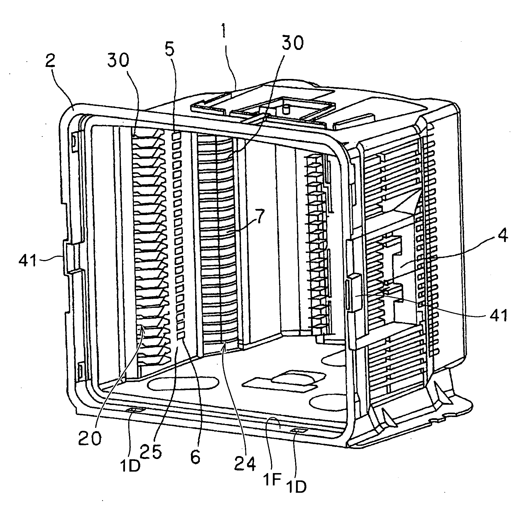
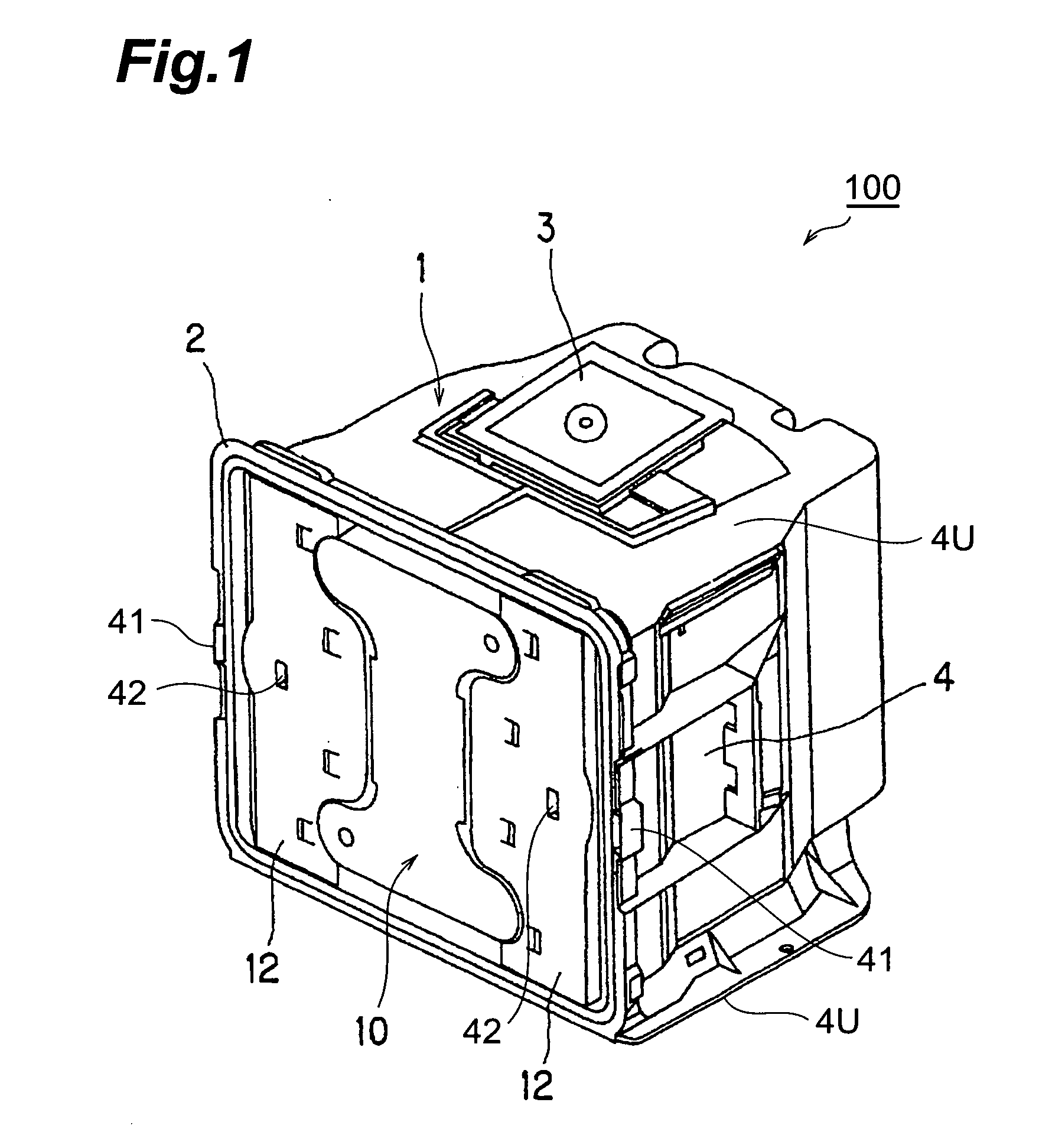
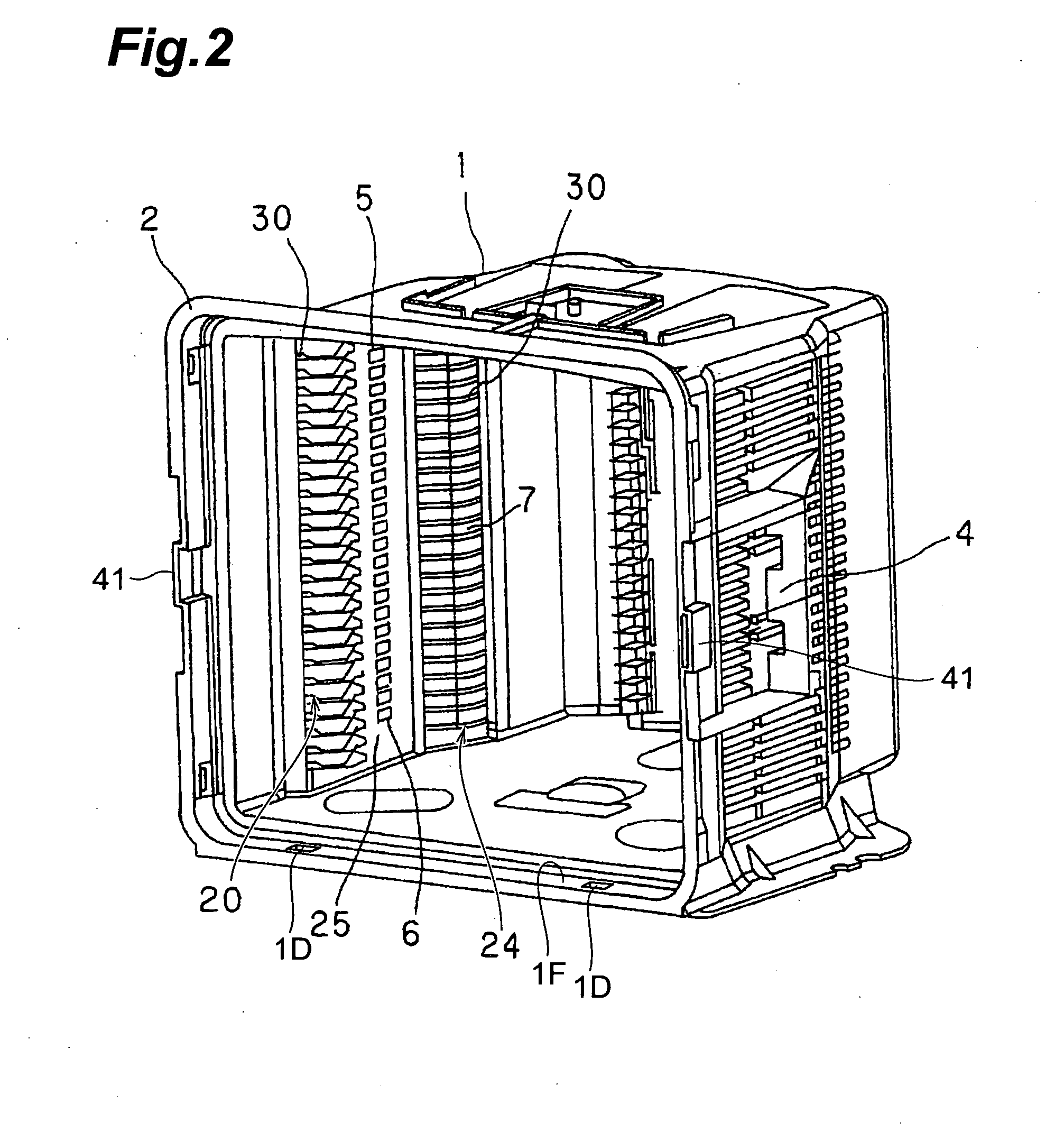
[0034] FIGS. 1 to 9 show a precision substrate storage container 100 used for shipping according to the first embodiment of the present invention. As shown in FIGS. 1 to 9, the substrate storage container 100 comprises a container main body 1, a lid member 10, a plurality of first supporting parts 20, and a plurality of second supporting parts 24.

[0035] A container main body 1 includes an opening portion 1F, a back wall 1B opposing the opening portion 1F, and two pairs of side walls 4 and side walls 4U, and the container main body 1 stores a plurality of substrates W between the side walls 4 and side walls 4U. The lid member 10 closes the front side of the container main body 1, which is the opening portion 1F of the container main body 1.

[0036] A plurality of first supporting parts 20 are respectively disposed on the pair of left and right side walls 4 forming par...


PUM


Abstract

A substrate storage container includes a container main body, first supporting parts and second supporting parts. The container main body includes a back wall and a pair of side walls in order to store a substrate between the side walls. The first supporting parts are opposingly disposed on each side wall in order to support a peripheral edge part of the substrate. The second supporting parts are opposingly disposed on each side wall in order to support the peripheral edge part of the substrate and positioned between the back wall and the first supporting parts. The first supporting parts and the second supporting parts are covered with a resin layer having a lower frictional property than that of the container main body.

Description

BACKGROUND OF THE INVENTION [0001] 1. Field of the Invention [0002] The present invention relates to a substrate storage container for storing various types of semiconductor wafers or substrates made of a photo-mask glass, a aluminum disc or the like. [0003] 2. Related Background of Art [0004] A conventional substrate storage containers, which is not shown in the drawings, includes a container main body in which a plurality of substrates including semiconductor wafers are arranged and stored, a lid member which can be freely attached and detached, and which opens and closes the front surface constituting the opening part of this container main body, and an anchoring mechanism which fastens the lid member that covers the front surface of the container main body. Such containers are utilized as precision substrate storage containers. A plurality of supporting parts are respectively disposed on the inside surfaces of both side walls of the container main body and have a shape bent alon...

Claims


Application Information

Patent Timeline
Patent Type & Authority Applications(United States)
IPC IPC(8): B65D85/00
CPCH01L21/67383H01L21/67369H01L21/02
Inventor HASEGAWA, AKIHIROMIMURA, HIROSHI
Owner SHIN-ETSU POLYMER CO LTD
Learn More