
Module and method for fabricating the same

Inactive Publication Date: 2006-12-07
EGUCHI SYUUJI +3
View PDF56 Cites 77 Cited by
  • Summary
  • Abstract
  • Description
  • Claims
  • Application Information

AI Technical Summary

Benefits of technology

[0008] Also, the module disclosed in JP-A-7-22722 has problems that a special mold structure and apparatus are required to hold the vacuum state, and that the use of the paste-like resin as a protective resin requires a curing time of several tens minutes and prolongs a time until a product is taken out of a mold. Another problem is that, because the protective resin having the thermal expansion coefficient matched with those of an electronic circuit board and electronic components has a very high viscosity in a state of the paste-like resin before curing, a high vacuum is required to pour the resin, and hence productivity is reduced.
[0011] An object of the present invention is to provide a module having a smaller size with enhanced reliability and productivity, and a method for fabricating the module.
[0013] Also, to achieve the above object, the present invention provides a module comprising a connector having metal terminals for connection, and a circuit board mounting electronic components, the connector and the board being connected to each other through metal leads, wherein (A) the surface of the connector on the side being connected to the board, the metal leads, and the electronic components are sealed with the same thermosetting resin, (B) the thermosetting resin is in solid state at temperatures of 40° C. or below before curing, (C) the thickness of the thermosetting resin sealing the electronic components is changed depending on the heights of the electronic components, and (D) the connector is disposed perpendicularly to a surface of the board being covered with the thermosetting resin sealing the electronic components or disposed on a surface of the board on the side opposite to the surface covered with the thermosetting resin. With those features, the module can be obtained in smaller size with enhanced reliability and productivity.

Problems solved by technology

However, the module disclosed in JP-A-2001-288333 has problems as follows.
These drawbacks give rise to a difficulty in handling and reduce productivity.
Also, the module disclosed in JP-A-7-22722 has problems that a special mold structure and apparatus are required to hold the vacuum state, and that the use of the paste-like resin as a protective resin requires a curing time of several tens minutes and prolongs a time until a product is taken out of a mold.
Another problem is that, because the protective resin having the thermal expansion coefficient matched with those of an electronic circuit board and electronic components has a very high viscosity in a state of the paste-like resin before curing, a high vacuum is required to pour the resin, and hence productivity is reduced.
Such a tendency to increase the module size is particularly noticeable in modules for use in automobiles and ships for the reasons that the leads are required to have a larger width and thickness from the viewpoint of connection to a connector on the connection receiving side, and that the known transfer molding has a difficulty in connecting the external terminal leads in parallel.
This may cause not only large warpage in the electronic equipment and module, but also stresses in the electronic components.
Particularly, problems may arise in causing crack rupture and peeling-off in the electronic equipment and module during mounting, and deteriorating reliability in a temperature cycle test, a thermal shock test, etc.

Method used


Image

  • Module and method for fabricating the same
  • Module and method for fabricating the same
  • Module and method for fabricating the same

Examples


first embodiment

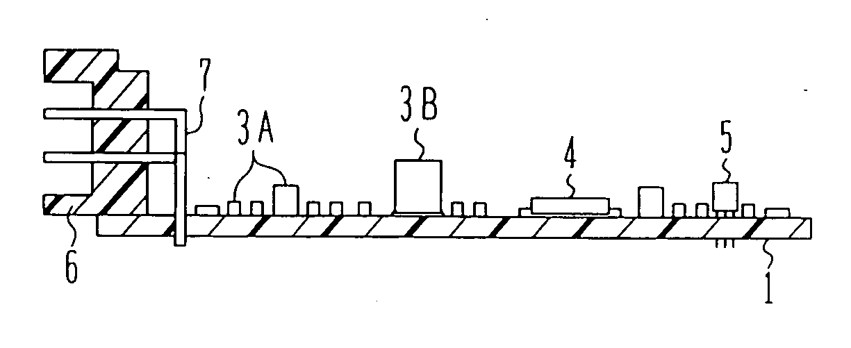
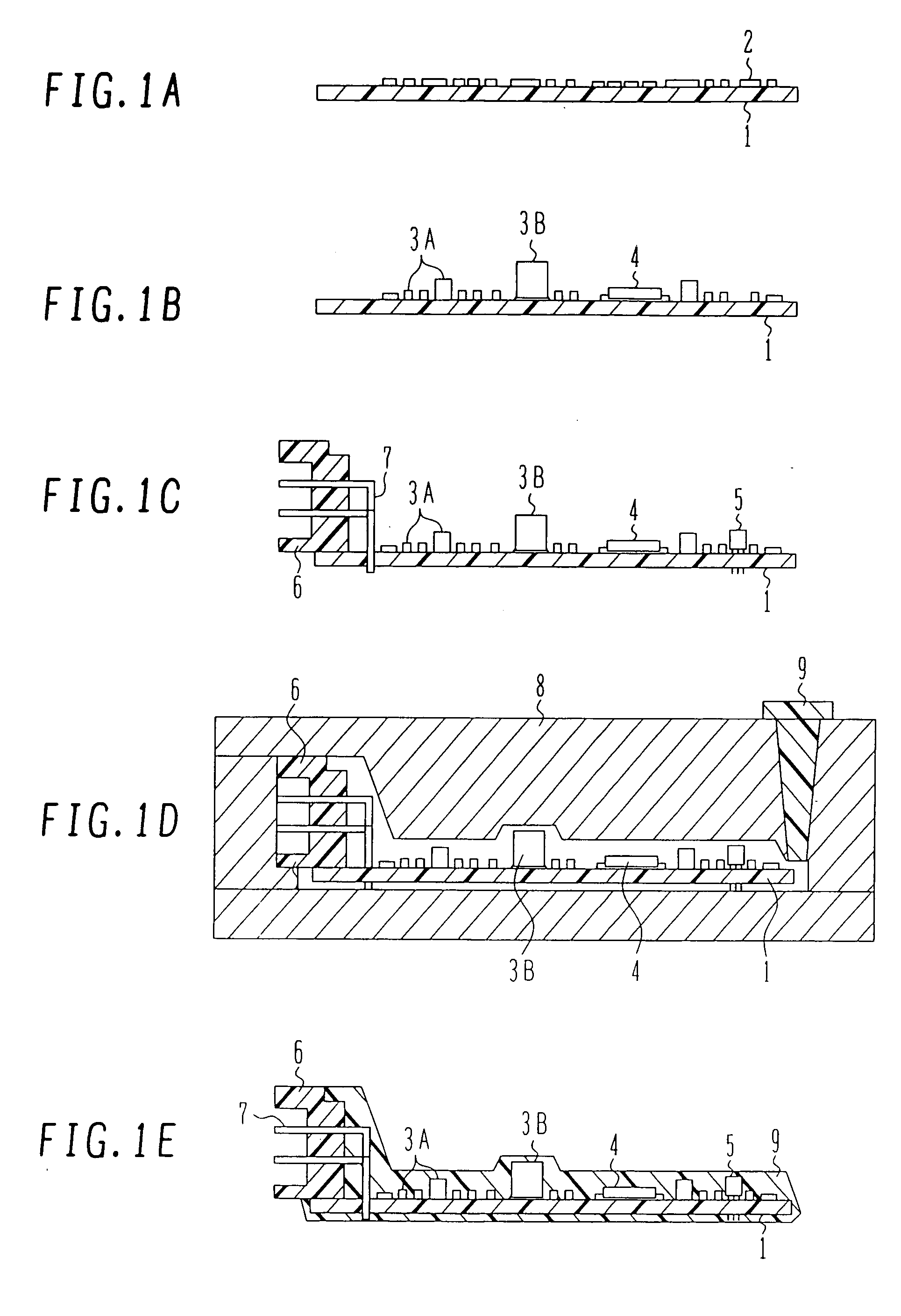
[0023] The construction of a module and a method for fabricating the module, according to the present invention, will be first described below with reference to FIGS. 1A-1E. The module of this embodiment is used as a control unit for automobiles, ships and motors, and a circuit board is formed of a two-layered resin printed board.

[0024]FIGS. 1A-1E illustrate successive steps of the method for fabricating the module according to the first embodiment of the present invention.

[0025] As shown in FIG. 1A, an Sn / Pb eutectic-crystal solder paste 2 is printed on one surface of a two-layered resin printed board 1. The resin printed board 1 has dimensions of 100×70 mm and has physical properties represented by the glass transition temperature of 130° C. and the linear expansion coefficient of 15 ppm / ° C.

[0026] Then, as shown in FIG. 1B, short (low height) chip components 3A, e.g., a chip resistor and a ceramic capacitor, a tall (high height) chip component 3B, e.g., an aluminum capacitor, a...

second embodiment

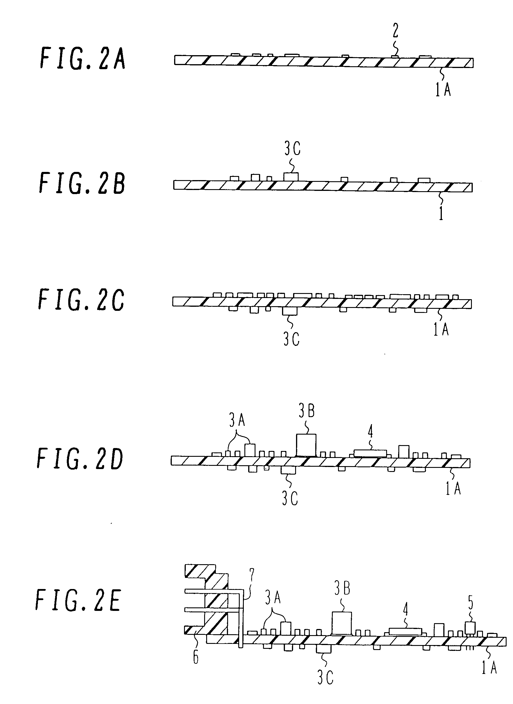
[0059] Next, the construction of a module and a method for fabricating the module, according to the present invention, will be described below with reference to FIGS. 2A-2G. The module of this embodiment is used as a control unit for automobiles, ships and motors, and a circuit board is formed of a four-layered resin printed board.

[0060]FIGS. 2A-2G illustrate successive steps of the method for fabricating the module according to the second embodiment of the present invention. Note that the same reference numerals as those in FIG. 1 denote the same members.

[0061] As shown in FIG. 2A, an Sn / Pb eutectic-crystal solder paste 2 is printed on one surface of a four-layered resin board 1A that has dimensions of 90×70 mm and has physical properties represented by the glass transition temperature of 170° C. and the linear expansion coefficient of 15 ppm / ° C.

[0062] Then, as shown in FIG. 2B, chip components 3C, e.g., a chip resistor and a ceramic capacitor, are mounted on the circuit board 1...

third embodiment

[0069] The construction of a module and a method for fabricating the module, according to the present invention, will be described below with reference to FIG. 3. The module of this embodiment is used as a control unit for automobiles, ships and motors, and a circuit board is formed of a four-layered resin printed board.

[0070]FIGS. 3A-3F illustrate successive steps of the method for fabricating the module according to the third embodiment of the present invention. Note that the same reference numerals as those in FIGS. 1 and 2 denote the same members.

[0071] As shown in FIG. 3A, an Sn / Ag / Cu solder paste 2A is printed on one surface of a four-layered resin board 1A that has dimensions of 100×70 mm and has physical properties represented by the glass transition temperature of 170° C. and the linear expansion coefficient of 15 ppm / ° C.

[0072] Then, as shown in FIG. 3B, chip components 3A, e.g., a chip resistor and a ceramic capacitor, a chip component 3B, e.g., an aluminum capacitor, a...


PUM

PropertyMeasurementUnit
Temperatureaaaaaaaaaa
Pressureaaaaaaaaaa

Abstract

A module having a smaller size with enhanced reliability and productivity, and a method for fabricating the module. The module comprises a connector (6) having metal terminals for connection, and a circuit board (1) mounting electronic components. The connector (6) and the board (1) are connected to each other through metal leads (7). The surface of the connector (6) on the side being connected to the board, the metal leads 7, and the electronic components are sealed with the same thermosetting resin (9). The thermosetting resin (9) is in solid state at temperatures of 40° C. or below before curing, and the thickness of the thermosetting resin (9) sealing the electronic components is changed depending on the heights of the electronic components.

Description

TECHNICAL FIELD [0001] The present invention relates to a module containing electronic components mounted on a board and sealed with a resin, and a method for fabricating the module. More particularly, the present invention relates to a module suitable for use as various control units and sensor modules in an automobile, and a method for fabricating the module. BACKGROUND ART [0002] Hitherto, various control units (e.g., an engine control unit, a motor control unit, and an automatic transmission control unit) in an automobile have been disposed in a compartment or an engine room. Those control units are generally structured such that electronic components are mounted on a printed board, and the printed board is fixed to a metal base and covered with a cover case. [0003] Recently, a control unit directly mounted on an intake manifold or the like, i.e., an on-engine type control unit, has been proposed. A control unit using a printed board is resistant against temperatures up to about...

Claims


Application Information

Patent Timeline
IPC IPC(8): H05K3/30H05K3/28
CPCH05K3/284Y10T29/49171Y10T29/49146H05K2201/10189H05K3/0061H05K3/0064H05K5/0034H05K5/0082H05K5/065H05K7/20854H05K2201/0191H05K2201/0209H05K2201/09072H05K2201/10734H05K2203/1316
Inventor EGUCHI, SYUUJIASANO, MASAHIKOSASAKI, MASAHIROUCHIYAMA, KAORU
Owner EGUCHI SYUUJI
Learn More