Hermetic compressor

Inactive Publication Date: 2006-01-26
SAMSUNG GWANGJU ELECTRONICS CO LTD
View PDF9 Cites 3 Cited by
  • Summary
  • Abstract
  • Description
  • Claims
  • Application Information

AI Technical Summary

Benefits of technology

[0011] The present invention has been made in view of the above mentioned problems, and an aspect of the invention is to provide a hermetic compressor having a discharge muffler which is improved in structure to achieve enhanced productivity and reliability.

Problems solved by technology

However, the conventional hermetic compressor configured as stated above has a problem in that the baffle must be present inside the discharge muffler, resulting in a complicated manufacturing process and high manufacturing cost.
Further, when the baffle is displaced out of its original installation position due to the pressure of the refrigerant, this hinders proper discharge of the refrigerant.

Method used


Image

  • Hermetic compressor
  • Hermetic compressor
  • Hermetic compressor

Examples


Embodiment Construction

[0028] Reference will now be made in detail to the embodiments of the present invention, examples of which are illustrated in the accompanying drawings, wherein like reference numerals refer to the like elements throughout.

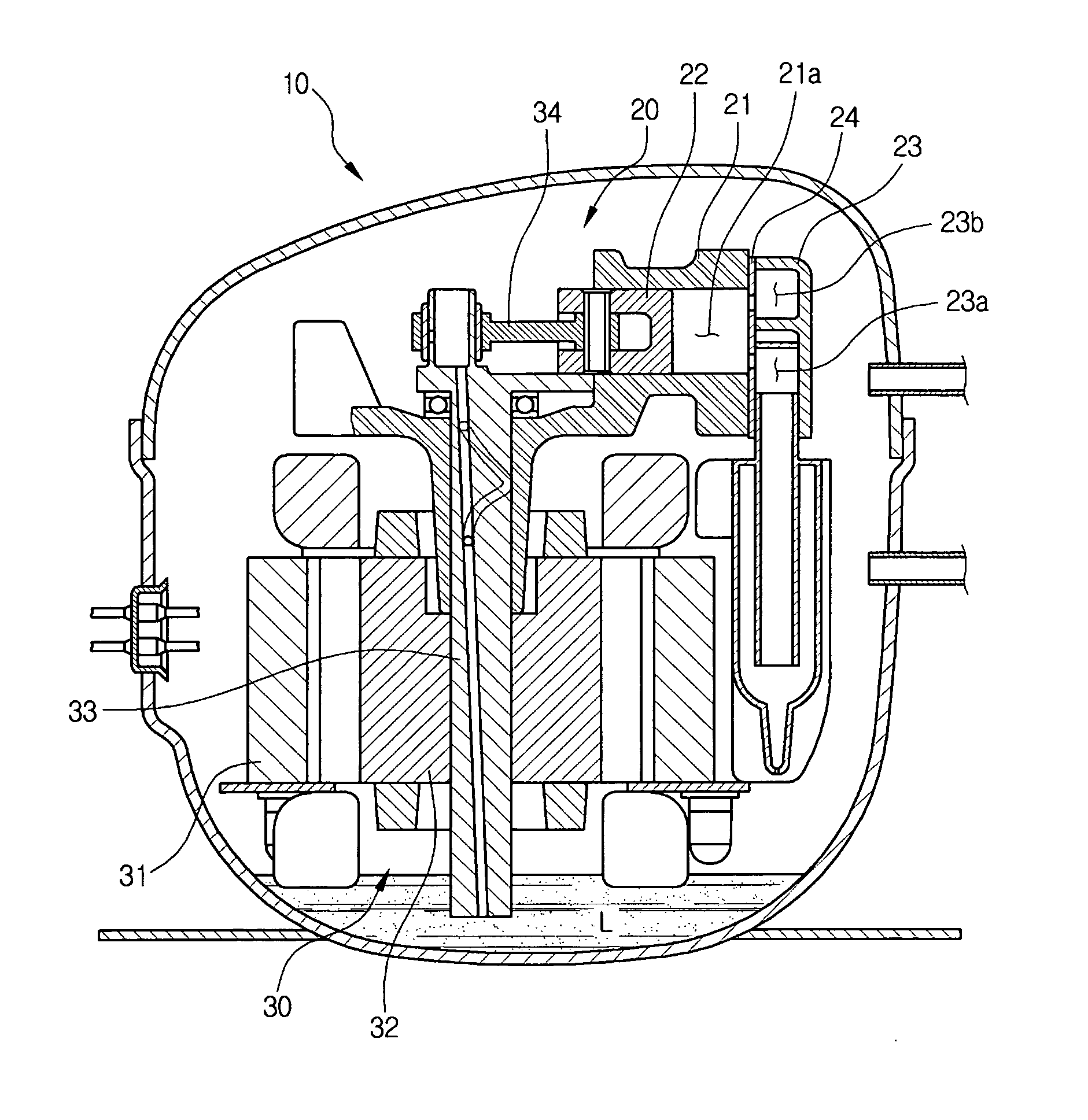
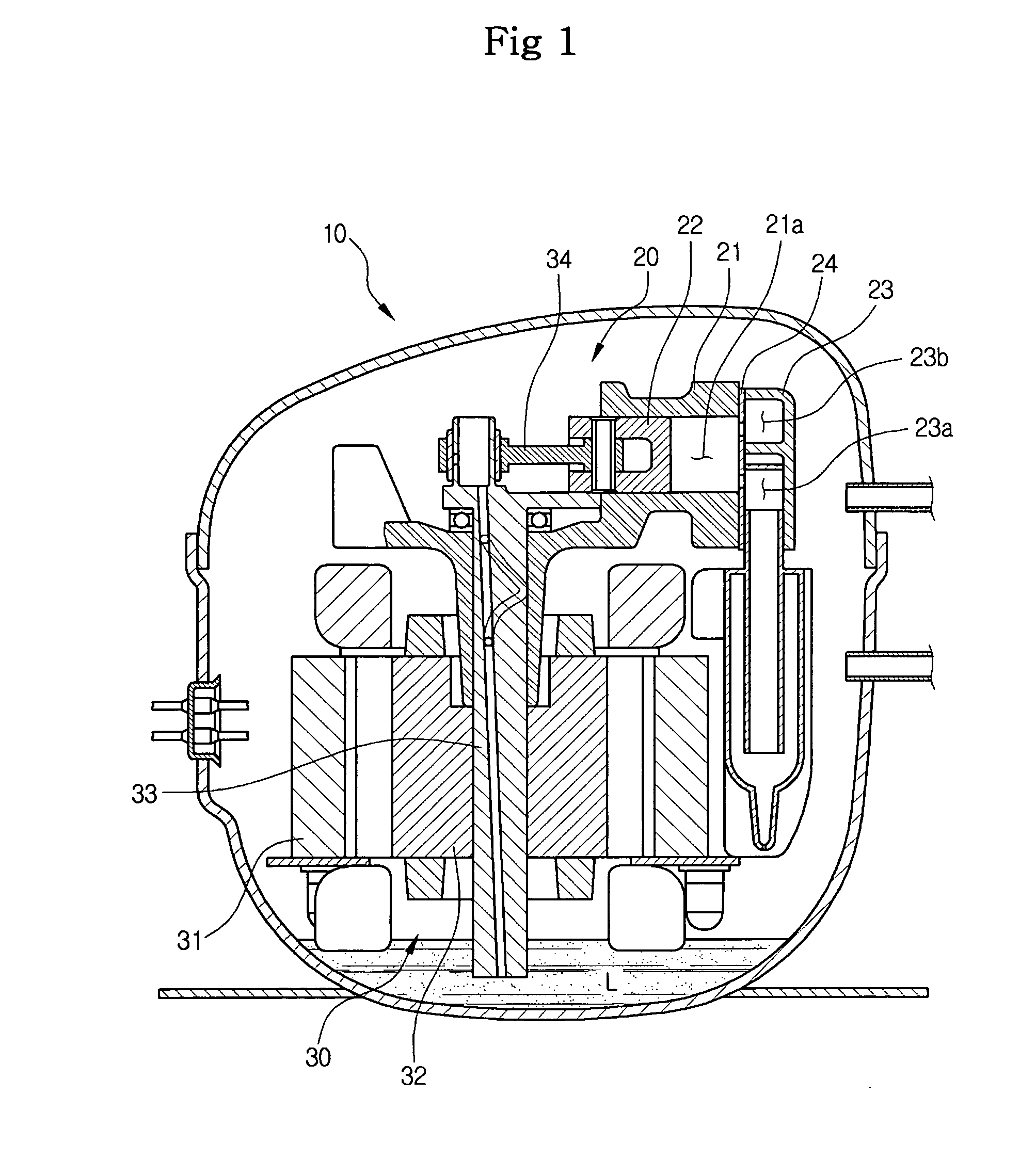
[0029]FIG. 1 is a side sectional view of a hermetic compressor in accordance with the present invention. Referring to FIG. 1, the hermetic compressor of the present invention comprises a compressing unit 20 disposed inside a hermetic casing 10 to compress a refrigerant, and a driving unit 30 to generate power required to drive the compressing unit 20.

[0030] The compressing unit 20 includes a cylinder block 21 internally defining a compression chamber 21a, and a piston 22 reciprocating inside the compression chamber 21a so as to suction, compress and discharge the refrigerant. A cylinder head 23 is disposed at one end of the cylinder block 21 to face each other. The cylinder head 23 internally defines a suction chamber 23a and a discharge chamber 23b. A valve uni...


PUM


Abstract

A hermetic compressor comprising a discharge muffler. The discharge muffler includes a dented muffler body defined in a cylinder block and a muffler cover to cover the muffler body. The muffler body has a partition to divide the interior of the discharge muffler into a pair of first and second resonance chambers. The partition is integrally formed with the muffler body upon casting of the cylinder block. The partition protrudes from a bottom surface of the muffler body toward the muffler cover so that it is spaced apart from the muffler cover, thereby defining a first communicating portion between the partition and the muffler cover. A refrigerant, introduced into the first resonance chamber, is compressed while passing through the first communicating portion, and is diffused in the second resonance chamber. In this way, the pulsation of the refrigerant is attenuated.

Description

CROSS-REFERENCE TO RELATED APPLICATION [0001] This application claims the benefit of Korean Patent Application No. 2004-56456, filed on Jul. 20, 2004 in the Korean Intellectual Property Office, the disclosure of which is incorporated herein by reference. BACKGROUND OF THE INVENTION [0002] 1. Field of the Invention [0003] The present invention relates to a hermetic compressor, and, more particularly, to a hermetic compressor having a discharge muffler capable of attenuating noise generated when a compressed refrigerant is discharged to the outside. [0004] 2. Description of the Related Art [0005] In general, a hermetic compressor is designed to suction a refrigerant into a hermetic casing thereof to compress it, and discharge the compressed refrigerant to the outside. Such a hermetic compressor comprises a compressing unit to compress the refrigerant and a driving unit to drive the compressing unit. [0006] The compressing unit is disposed inside the hermetic casing, and includes a cyl...

Claims


Application Information

Patent Timeline
IPC IPC(8): F04B11/00A61M1/00
CPCF04B39/0061
Inventor SEO, CHEOL
Owner SAMSUNG GWANGJU ELECTRONICS CO LTD
Why Eureka
Try Eureka