Eureka AIR delivers breakthrough ideas for toughest innovation challenges, trusted by R&D personnel around the world.

Flashback Suppression System for a Gas Turbine Combustor

a gas turbine and combustor technology, applied in the field of gas turbine combustors, can solve the problems of increasing so as to improve the flashback margin, and reduce the risk of combustion failur

Active Publication Date: 2006-11-23
H2 IP UK LTD
View PDF5 Cites 31 Cited by
  • Summary
  • Abstract
  • Description
  • Claims
  • Application Information

AI Technical Summary

Benefits of technology

"The gas turbine combustor described in this patent has a premix chamber and a combustion chamber with a flashback margin. To prevent flashback, an inert gas is introduced into the boundary layer between the two chambers. This inert gas purging prevents a combustible reaction from occurring and being sustained in the boundary layer should flashback occur. The inert gas has little impact on the combustor or engine performance while improving flashback margin."

Problems solved by technology

While premixing fuel and compressed air prior to combustion has its advantages in terms of emissions, it also has certain disadvantages such as combustion instabilities.
More specifically, premix combustion stability issues of concern include combustion dynamics and flashbacks.
Therefore, fuel-lean mixtures tend to be more unstable given the lesser fuel content for a given amount of air.
As a result, when fuel-lean mixtures are burned they tend to produce greater pressure fluctuations due to the unstable flame.
In operation, if a combustor flashes back, the flashback can cause significant damage to combustor hardware if going undetected, possibly requiring premature replacement or repair.
Furthermore, a flashback can affect engine performance by unexpectedly reducing power output.
However, for high flame speed fuels, establishing flashback margin, can require extremely high velocities, which in turn results in high combustion pressure drop and hence deterioration of engine efficiency.

Method used


Image

  • Flashback Suppression System for a Gas Turbine Combustor
  • Flashback Suppression System for a Gas Turbine Combustor
  • Flashback Suppression System for a Gas Turbine Combustor

Examples


Embodiment Construction

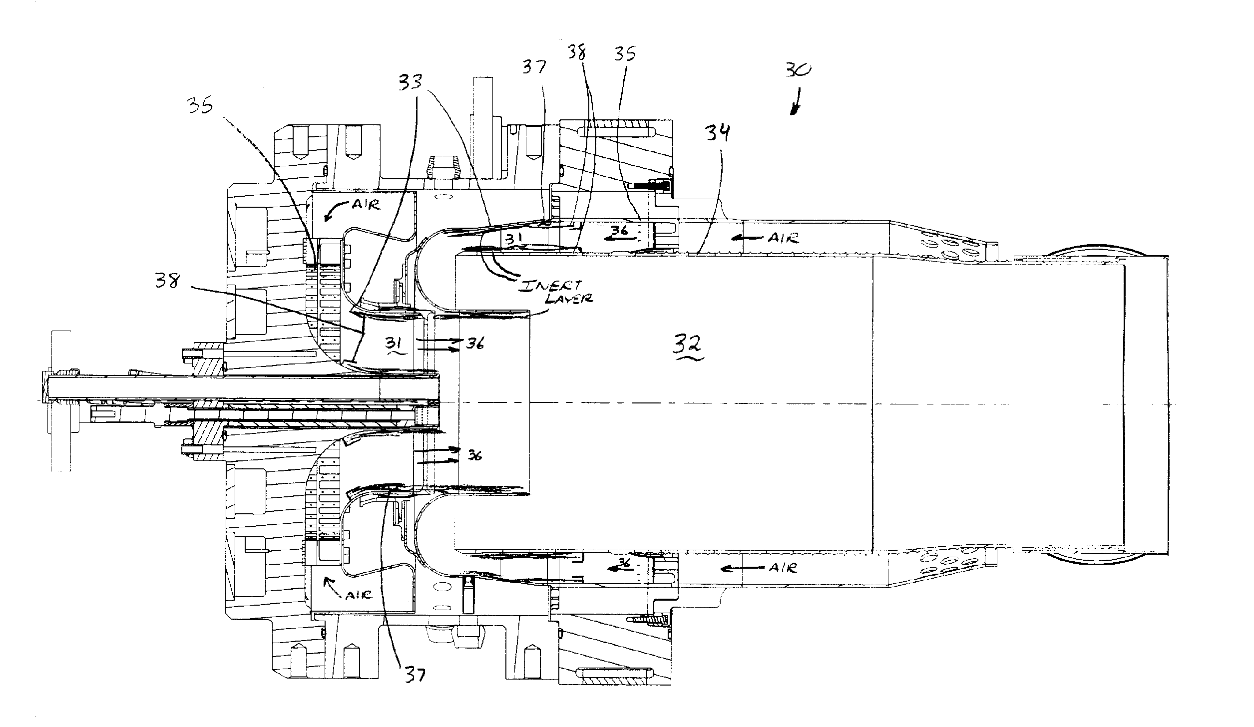
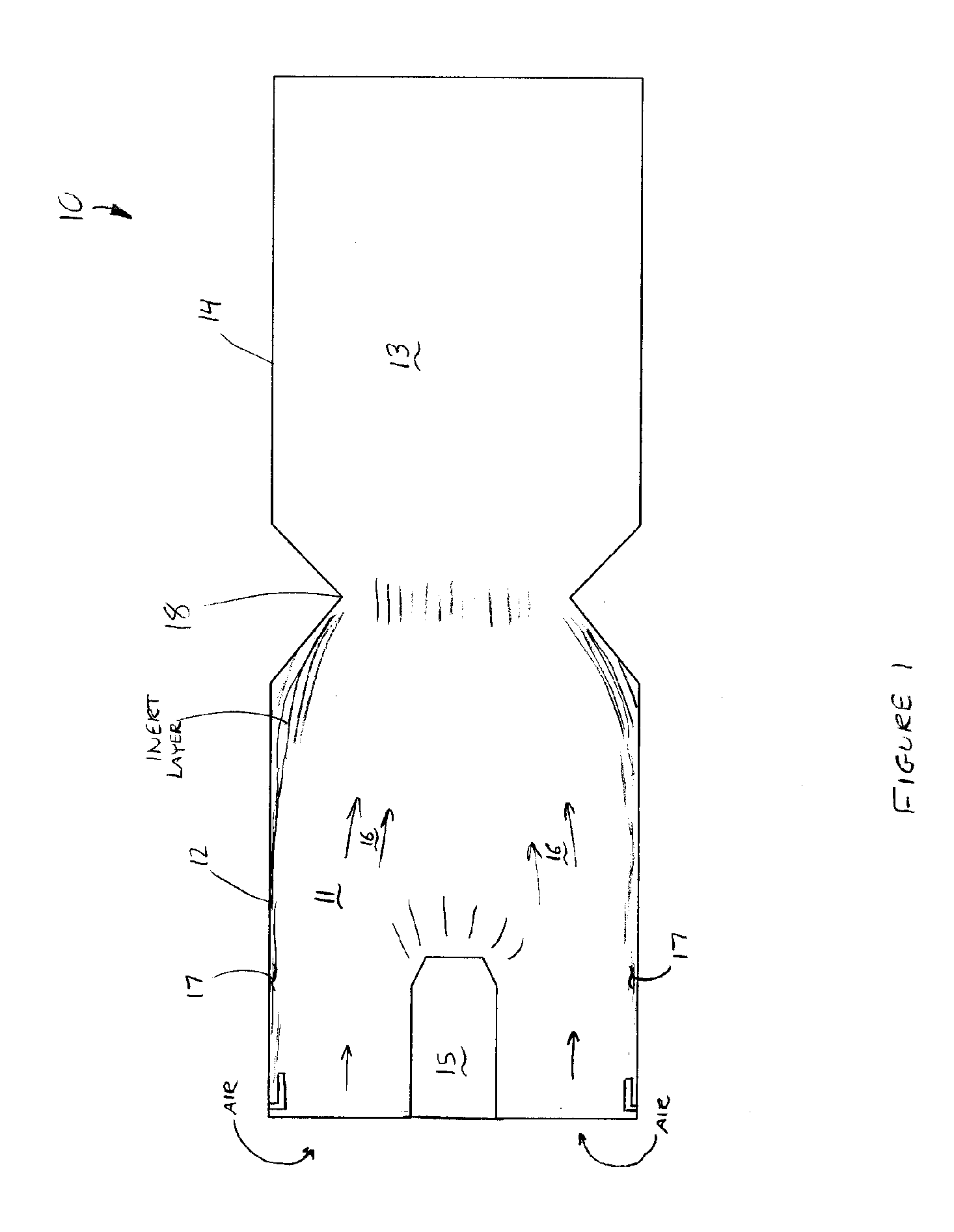
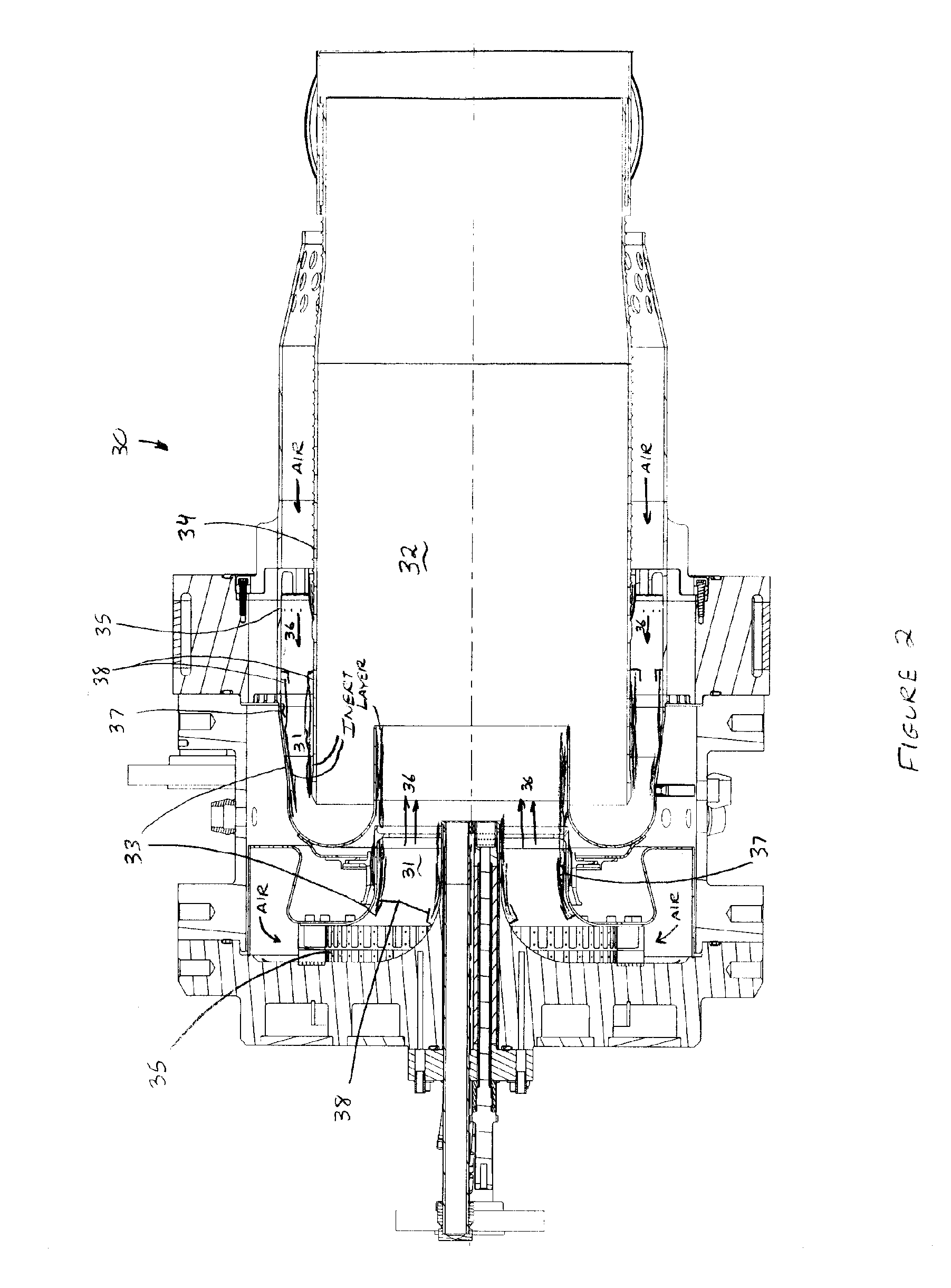
[0010] The present invention will now be described in detail with reference to FIGS. 1-3. Referring now to FIG. 1, the preferred embodiment of the present invention is shown in cross section. A gas turbine combustor 10 comprises premix chamber 11 having a first generally annular wall 12 and combustion chamber 13 having a second generally annular wall 14, with combustion chamber 13 in fluid communication with premix chamber 11.

[0011] Combustor 10 further comprises at least one fuel nozzle 15 for injecting a fuel into premix chamber 11 to form a mixture 16 with compressed air in premix chamber 11. For the purposes of a gas turbine engine, the compressed air is preferably delivered to combustor 10 from the engine compressor. As for the fuel type injected into the premix chamber, a variety of fuels can be used depending on fuel availability, operating conditions, and desired emissions levels. The fuel is preferably selected from the group comprising natural gas, liquid fuel, gas from c...


PUM


Abstract

A gas turbine combustor having improved flashback margin is disclosed. Multiple embodiments of the present invention are disclosed including combustors having a single premix chamber as well as multiple premix chambers. Flashback margin is increased for the combustor by incorporating a means for introducing an inert gas, such as nitrogen, into the premix chamber(s) at the region proximate the boundary layer to purge the boundary layer of combustible mixture, thereby ensuring that no combustion reaction occurs in the boundary layer.

Description

BACKGROUND OF THE INVENTION [0001] The present invention relates in general to gas turbine combustors and more specifically to premixed combustors having improved flashback margin. [0002] In a combustion system for a gas turbine, fuel and compressed air are mixed together and ignited to produce hot combustion gases that drive a turbine and produce thrust or drive a generator for producing electricity. In an effort to reduce pollution levels, government agencies have introduced new regulations requiring gas turbine engines to reduce emitted levels of emissions, including carbon monoxide and oxides of nitrogen (NOx). A common type of combustion, employed to comply with these new emissions requirements, is premix combustion, where fuel and compressed air are mixed together prior to ignition to form as homogeneous a mixture as possible and burning this mixture to produce lower emissions. While premixing fuel and compressed air prior to combustion has its advantages in terms of emissions...

Claims


Application Information

Patent Timeline
Patent Type & Authority Applications(United States)
IPC IPC(8): F23R3/30
CPCF23D14/82F23L7/00F23R3/286F23R3/24F23L2900/07002
Inventor STUTTAFORD, PETER JOHN
Owner H2 IP UK LTD
Why Eureka
Eureka Blog
Learn More