
Field effect transistor with novel field-plate structure

a field-plate structure and transistor technology, applied in transistors, semiconductor devices, electrical devices, etc., can solve the problems of large leakage current through the channel, large electrical field formation region in the channel underneath the gate electrode, and reduce the maximum output current and hence the maximum output power of the device, and achieve high reliability. the effect of high breakdown voltag

Inactive Publication Date: 2006-11-16
WIN SEMICON
View PDF4 Cites 14 Cited by
  • Summary
  • Abstract
  • Description
  • Claims
  • Application Information

AI Technical Summary

Benefits of technology

[0008] Accordingly, it is an objective of the present invention to provide a novel Schottky gate FET structure with a field plate thereon, which makes the device to have a high breakdown voltage with a high confidence level of reliability.
[0009] It is also an objective of the present invention to provide a novel Schottky gate FET structure with a field plate thereon being capable of high-frequency and high-output-power operations.
[0010] Another and more specific objective of the present invention is to provide a novel Schottky gate FET structure with a field plate thereon that can eliminate surface damages of unpassivated region and degradation of the interface property of gate contacts during plasma etching of dielectric film for gate recesses.

Problems solved by technology

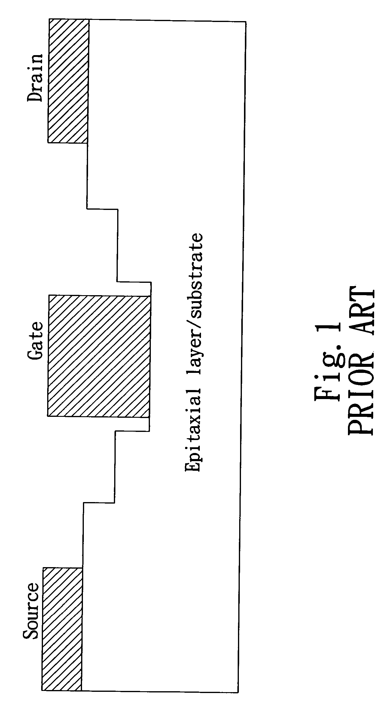
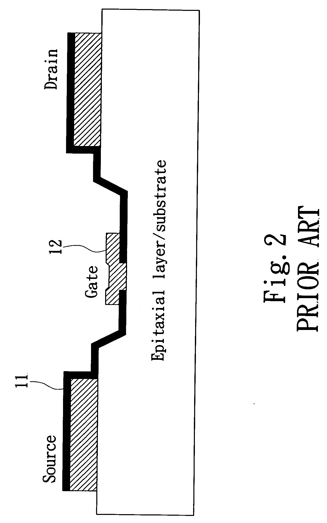
However, when the Schottky gate junction is biased at higher voltages, a region of huge electric field will be formed in the channel underneath the gate electrode, particularly in the vicinity of the drain edge.
Such a large electric field will lead to an avalanche breakdown in the channel region between the gate and the drain electrodes, and therefore induce a large leakage current through the channel.
This problem is particularly important for large-signal and high-output operations since the device performance is obviously limited by the breakdown voltage and the leakage current.
However, larger gate-drain distance will also lead to larger source-drain resistance, which in effect reduces the maximum output current and hence the maximum output power from the device.
However, the drawback of this approach is that a device of high breakdown voltage tends to suffer from a significant gate-lag.
Consequently, even with high breakdown voltage, it is difficult to achieve high output power using the double-recess approach.
However, it is difficult to control plasma damage during the gate recess undercut, which inevitably degrades the interface property of the gate contact as well as the surface of the unpassivated region.
Consequently, the device reliability suffers frequently.

Method used


Image

  • Field effect transistor with novel field-plate structure
  • Field effect transistor with novel field-plate structure
  • Field effect transistor with novel field-plate structure

Examples


Embodiment Construction

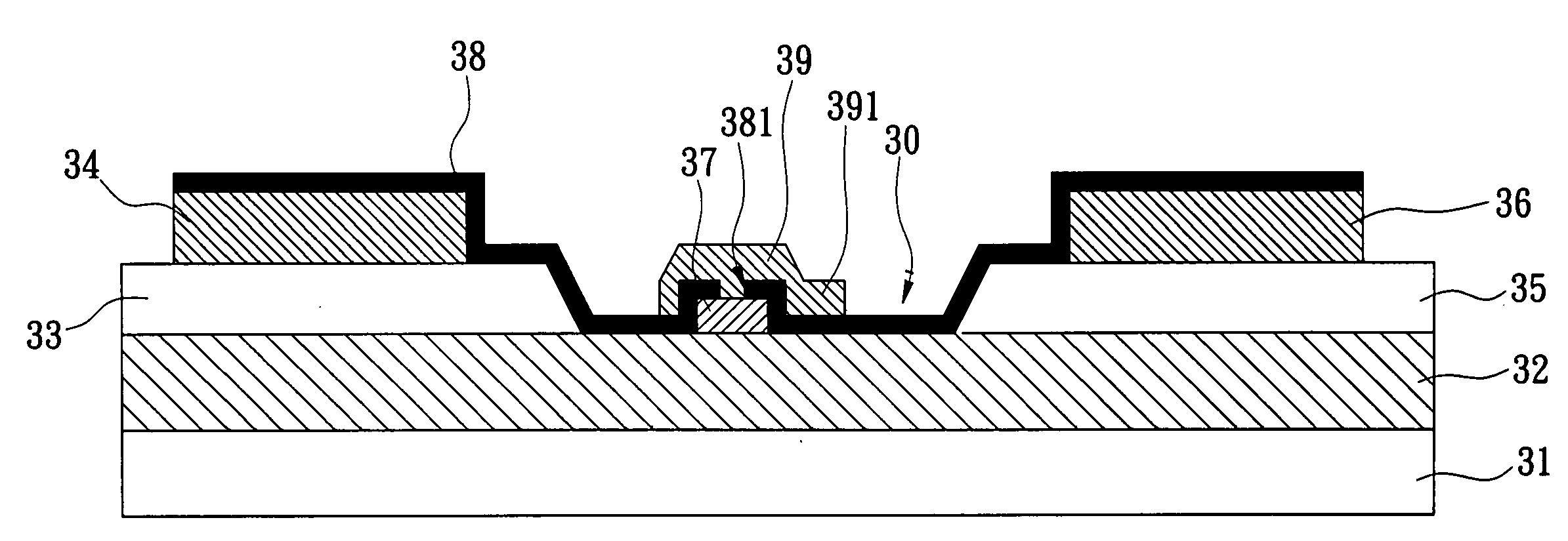
[0016]FIG. 3 is a cross-section view of the novel Schottky gate FET structure with a field plate thereon of the present invention. The semiconductor layer structure in FIG. 3 generally comprises a substrate 31 and a channel layer 32 thereon, whereon a contact layer is formed. The contact layer has a source region 33, a drain region 35 with a distance apart from the source region 33 and a recess region 30 being formed by removing the part of the contact layer between the source and the drain regions 33, 35. A source electrode 34 and a drain electrode 36 are formed on the source region 33 and the drain region 35, respectively. Both the source and the drain electrodes 34, 36 make an ohmic contact with the contact layer, and being electrically coupled to the channel layer 32 underneath. On the recess region 30 of the contact layer, a gate electrode 37, having a finger shape, is formed and making a Schottky contact with the channel layer 32 underneath. After the formation of the source, ...


PUM


Abstract

A field effect transistor (FET) with novel field-plate structure relates to a Schottky gate FET structure with field plate thereon for increasing the operation voltage. The structure can eliminate surface damages of unpassivated region and degradation of the interface property of gate contacts during plasma etching of dielectric film for gate recesses, and can be reliably used in wireless and satellite communications.

Description

BACKGROUND OF THE INVENTION [0001] 1. Field of the Invention [0002] The present invention relates to a field-effect transistor (FET), more particularly, relates to a Schottky gate FET structure with field plate thereon for increasing the operation voltage, which can be reliably used in wireless and satellite communications. [0003] 2. Description of the Prior Art [0004] High-power and high-speed semiconductor device operating at microwave frequency is the key component used in wireless and satellite communications. Compound semiconductor Schottky gate FETs, such as GaAs metal-semiconductor FETs (MESFET), high electron mobility transistor (HEMT) as well as pseudomorphic HEMT (p-HEMT), are well known devices for such applications. For a conventional Schottky gate FET, a metal electrode is directly contacted to the semiconductor, forming a Schottky gate junction. When a voltage is applied to the Schottky junction of the gate electrode, the current flow from drain to source electrodes th...

Claims


Application Information

Patent Timeline
IPC IPC(8): H01L31/112H01L29/80
CPCH01L29/402H01L29/8128H01L29/42316
Inventor TU, DER-WEI
Owner WIN SEMICON
Learn More