Memory control system

Inactive Publication Date: 2006-11-02
CS TECH CO LTD
View PDF5 Cites 6 Cited by
  • Summary
  • Abstract
  • Description
  • Claims
  • Application Information

AI Technical Summary

Benefits of technology

[0023] Accordingly, the present invention has been made keeping in mind the above problems occurring in the prior art, and an object of the present invention is to provide a memory control system that is less influenced by the size of an image block in a process of compressing image data, incurs no clock consumption, and has a simple structure and a simple calculation procedure.

Problems solved by technology

In order to access three or fewer pieces of data, a RAS command must be performed on the second bank Bank1142b between a RAS command and a CAS command performed on the first bank Bank0142a, so that a problem arises in that the structure of the SDRAM controller 130 is complicated.
Furthermore, another problem arises in that, when tRCDs are not guaranteed, the conventional memory control system must be provided with an additional circuit for guaranteeing tRCDs.
As the size of the image block of FIG. 1 becomes smaller, the above-described problems of the conventional memory control system become prominent.
In particular, a compression method, such as H.264, uses a 2×2 size image block, so that the problems of the conventional memory control system are more serious.
Meanwhile, it is impossible for the conventional memory control system to make single access that connects two or more banks.
Accordingly, when the master makes access, unnecessary time delay occurs and the circuit of the bus master is complicated.
However, the conventional memory control system is problematic in that it is difficult for a single master to request access to a plurality of image lines at one time.

Method used


Image

  • Memory control system
  • Memory control system
  • Memory control system

Examples


Embodiment Construction

[0036] Reference now should be made to the drawings, in which the same reference numerals are used throughout the different drawings to designate the same or similar components.

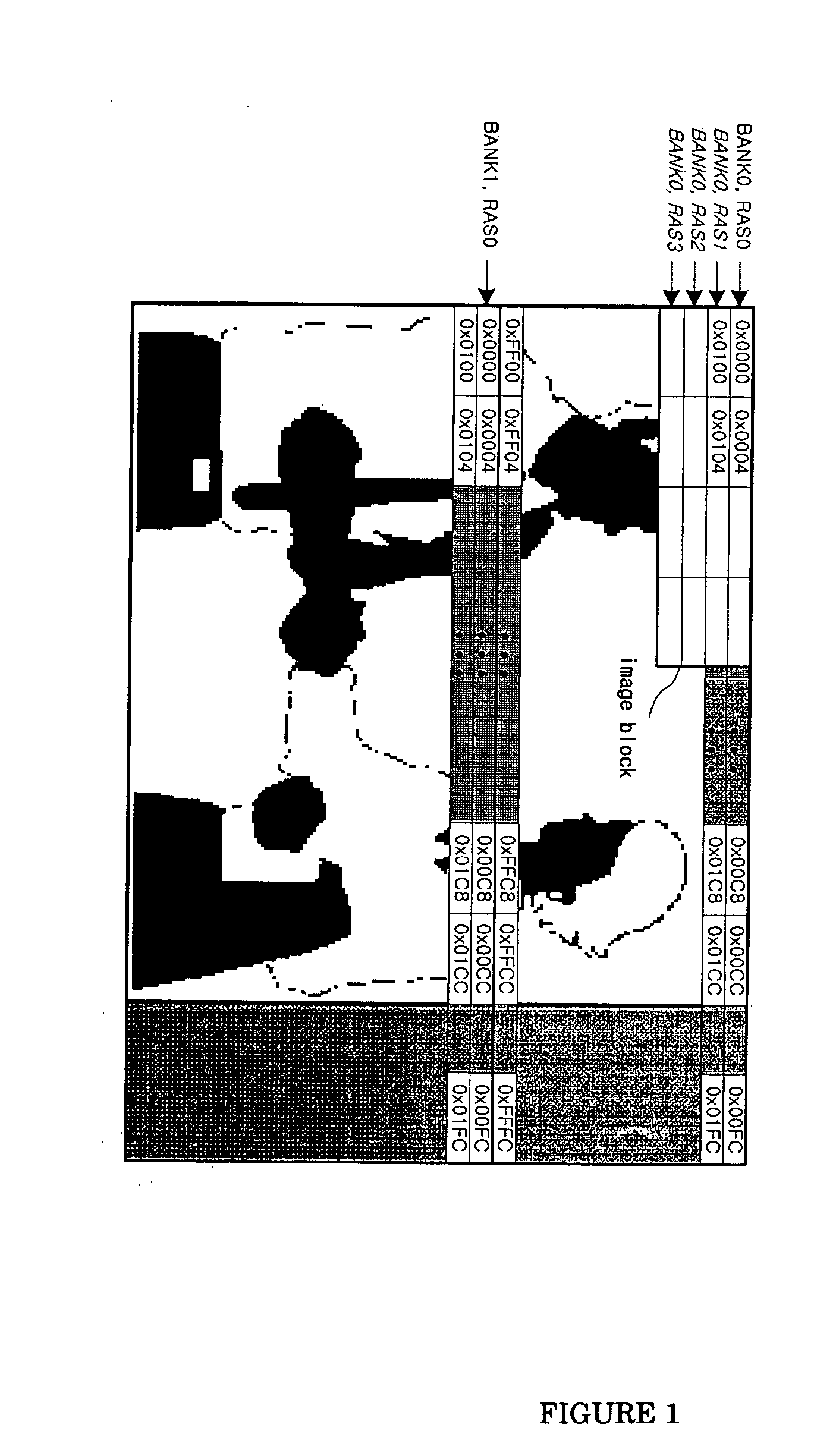
[0037]FIG. 4 illustrates the concept of the operation of a memory control system according to the present invention. A one-frame image is shown on the left side of FIG. 4, the state of image data stored in memory by the operation of the memory control system of the present invention is shown at the center of FIG. 4, and image data that have been stored in the memory and are read by the operation of the memory control system of the present invention are shown on the right side of FIG. 4.

[0038] Respective pieces of image data corresponding to respective image lines shown on the left side of FIG. 4 are stored in different banks, as shown at the center of FIG. 4. That is, image data corresponding to the first image line Image Line0 of a frame are stored in a region corresponding to the first row address RAS0 of...


PUM


Abstract

The memory control system includes a memory unit, bus master(s), arbiter, and memory controller. The bus masters output bus use request signals, block mode signals, block information, and drive information for data and outputs data corresponding to block / receive read-out data. The arbiter receives request signals and drive information and outputs a master selection signal used to select a bus master to which access is permitted and the drive signal input from the selected bus master. The bus master selection unit receives block mode signals, block information and data corresponding to the bus masters and outputs the block mode signal, block information and bus master data selected according to the master selection signal. The memory controller receives drive information from the arbiter, block mode signal, and block information from the selection unit, and allows data corresponding to respective line block groups to be sequentially-stored in / read out from respective banks.

Description

BACKGROUND OF THE INVENTION [0001] 1. Field of the Invention [0002] The present invention relates generally to a memory control system and, more particularly, to a memory control system including an arbiter. [0003] 2. Description of the Related Art [0004] Mobile communication equipment, including a recent Digital Multimedia Broadcasting (DMB) receiver, processes various multimedia signals, which are received from the earth or a satellite, in a digital manner and compresses image data to process the image data at high speed. [0005] The compression of image data is performed through the detection of the motion information of the images that constitute respective frames. A general method of compressing image data using motion information as described above is performed as described below. [0006] First, the difference elements between a reference image block included in a current frame and comparative image blocks included in previous frames are calculated, and a comparative image block...

Claims


Application Information

Patent Timeline
IPC IPC(8): G11C7/10G06F12/00G06F12/02G06F12/06G06T1/60H04N19/423H04N19/50H04N19/503
CPCG06F13/1605G06F12/00G06F13/14G06F13/16
Inventor JEONG, KYUNG AH
Owner CS TECH CO LTD
Why Eureka
Try Eureka