
Flat lamp device with multi electron source array

Inactive Publication Date: 2006-11-02
LEE SEUNG HO
View PDF3 Cites 24 Cited by
  • Summary
  • Abstract
  • Description
  • Claims
  • Application Information

AI Technical Summary

Benefits of technology

[0008] The present invention is designed in consideration of such problems of the prior art, and therefore it is an object of the present invention to provide a flat lamp device with excellent light emission uniformity so as to be used for a large-sized flat display or the like.
[0009] Another object of the present invention is to provide a flat lamp device that may give high brightness and relatively smaller exothermicity with low energy consumption.
[0010] Still another object of the present invention is to provide a flat lamp device with a structure capable to manufacture a slim display with a large size.
[0014] In addition, a light emission improving film may be further attached to an upper surface of the upper glass plate so as to improve light emission uniformity of the emitted light.

Problems solved by technology

CCFL and EEFL using fluorescent lamps have properties of long life and excellent light emission efficiency, but they also show high energy consumption and high exothermic property.
In addition, they have a limit in increasing their size, not suitable as a light source for a large-sized display.
In addition, CCFL and EEFL are not friendly to environments due to the use of mercury.
Moreover, LED is excellent in realizing colors, but has drawbacks of low efficiency and expensive manufacture costs.
FFL shows high brightness and excellent light efficiency, but it gives a relatively short long life cycle and insufficient for mass production.
FFL also has a drawback of using mercury.

Method used


Image

  • Flat lamp device with multi electron source array
  • Flat lamp device with multi electron source array
  • Flat lamp device with multi electron source array

Examples


Embodiment Construction

[0026] Hereinafter, preferred embodiments of the present invention will be described in detail with reference to the accompanying drawings. Prior to the description, it should be understood that the terms used in the specification and appended claims should not be construed as limited to general and dictionary meanings, but interpreted based on the meanings and concepts corresponding to technical aspects of the present invention on the basis of the principle that the inventor is allowed to define terms appropriately for the best explanation. Therefore, the description proposed herein is just a preferable example for the purpose of illustrations only, not intended to limit the scope of the invention, so it should be understood that other equivalents and modifications could be made thereto without departing from the spirit and scope of the invention.

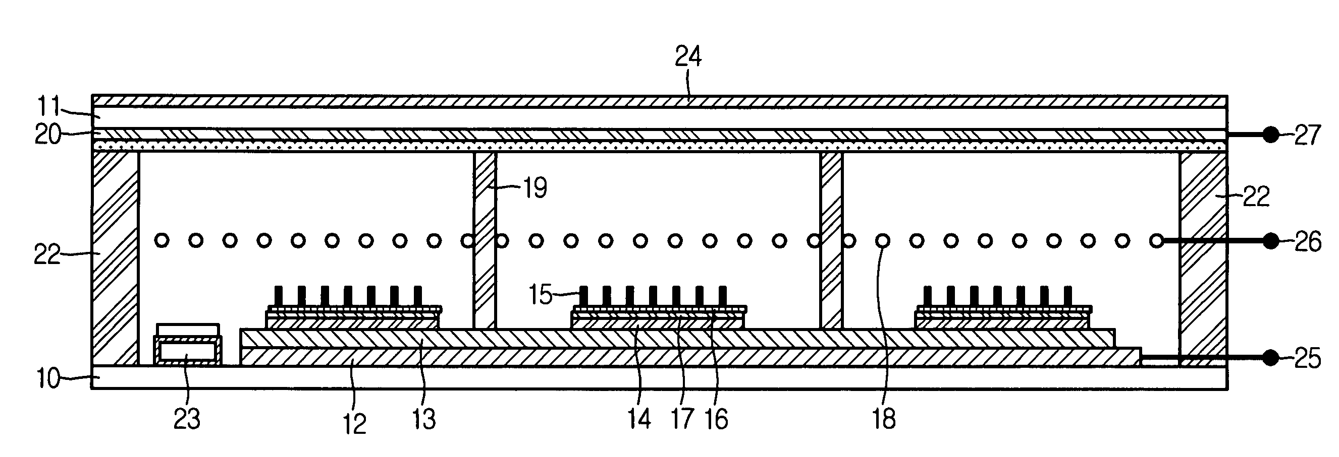
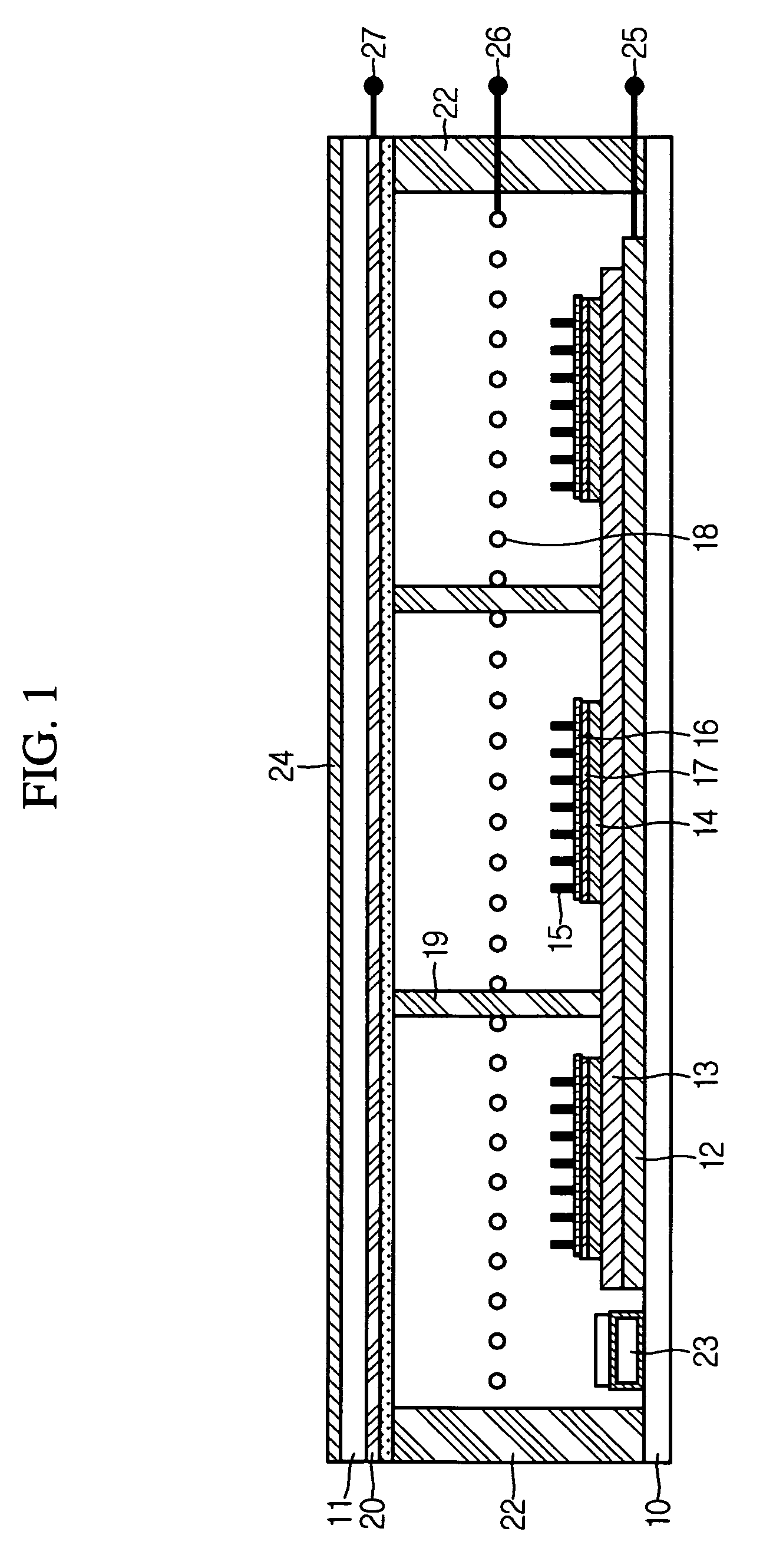
[0027] A flat lamp device of the present invention may be used as a backlight module of an LCD panel. FIG. 1 is a sectional view showing...


PUM


Abstract

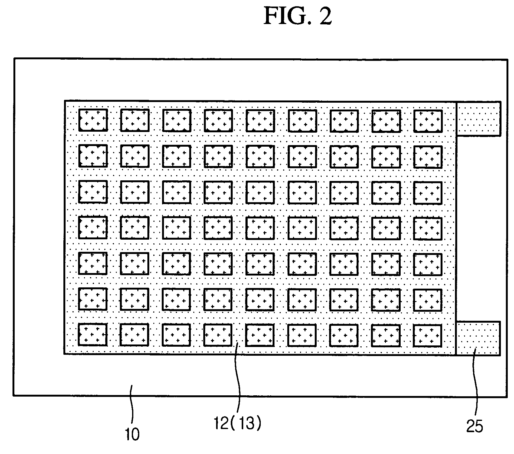
Disclosed is a flat lamp device, including lower and upper glass plates facing each other in parallel; spacers interposed between the plates to keep distance therebetween; a cathode electrode singly formed over the entire upper surface of the lower glass plate; an insulation film formed on the cathode electrode; semiconductor films independently patterned on the insulation film at intervals; a catalyst-metal layer laminated on the buffer metal to improve the adhesion of catalyst metal formed on the semiconductor films; carbon nano-tubes formed on the catalyst-metal layer; a grid electrode installed on the carbon nano-tubes between the plates to guide electron emission from the carbon nano-tubes with a mesh shape having an opening for passage of the emitted electrons; an anode electrode formed below the upper glass plate to accelerate the emitted electrons; and a fluorescent layer formed below the anode electrode to emit light by collision with the accelerated electrons.

Description

BACKGROUND OF THE INVENTION [0001] 1. Field of the Invention [0002] The present invention relates to a flat lamp device, and more particularly to an improved flat lamp device capable of uniformly emitting light having high brightness with low energy consumption by adopting a plurality of electron sources having independent patterns. [0003] 2. Description of the Related Art [0004] Generally, a flat display such as an LCD panel requires a separate backlight module in order to realize an image since it is not an active lamp device. Such a backlight module should form a flat light emission configuration so as to give uniform brightness over the entire area. In particular, as LCD panels get larger recently, the uniformity of brightness becomes more essential. [0005] Conventionally, as a backlight source, there have been used a Cold Cathode Fluorescent Lamp (CCFL), an External Electrode Fluorescent Lamp (EEFL), a Light Emission Diode (LED), a Flat Fluorescent Lamp (FFL) and so on. [0006] ...

Claims


Application Information

Patent Timeline
IPC IPC(8): H01J1/62
CPCH01J63/06H01J63/02H05B33/26
Inventor LEE, SEUNG-HO
Owner LEE SEUNG HO
Learn More