
Internal combustion engine knock determination device

a technology of knock determination and internal combustion engine, which is applied in the direction of measurement devices, rapid change measurement, instruments, etc., can solve the problems of vibration of internal combustion engine, and achieve the effect of high accuracy

Active Publication Date: 2006-11-02
TOYOTA JIDOSHA KK +2
View PDF4 Cites 27 Cited by
  • Summary
  • Abstract
  • Description
  • Claims
  • Application Information

AI Technical Summary

Benefits of technology

The present invention provides a knocking determination device for an internal combustion engine that can accurately determine whether knocking has occurred. The device includes a detecting unit that detects vibrations caused by combustion in the engine, and a determining unit that determines whether knocking has occurred based on the detected vibrations. The detecting unit is placed at a detection position in the engine and detects vibrations in the cylinder that correspond to resonance modes of combustion pressure propagation. By extracting the vibration of the resonance modes that correspond to knocking, the device can accurately determine whether knocking has occurred. This allows for the detection of knocking with high accuracy, even in the early stages of combustion.

Problems solved by technology

The resonance of in-cylinder pressure results in vibrations of the internal combustion engine.

Method used


Image

  • Internal combustion engine knock determination device
  • Internal combustion engine knock determination device
  • Internal combustion engine knock determination device

Examples


first embodiment

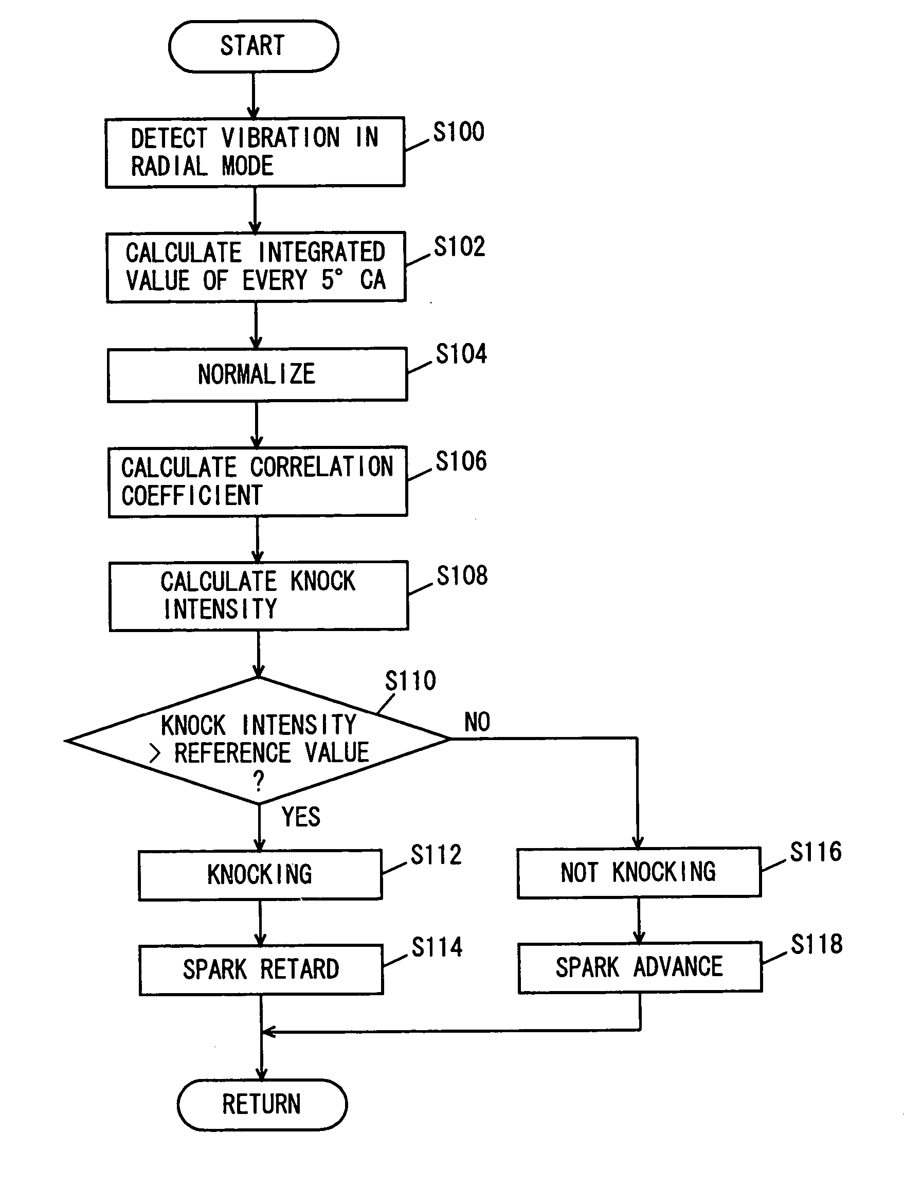
[0049] With reference to FIG. 1, an engine 100 of a vehicle incorporating a knock determination device according to an embodiment of the present invention will be described. The knock determination device of the present embodiment is implemented by a program executed, for example, by an engine ECU (Electronic Control Unit) 200.

[0050] Engine 100 is an internal combustion engine, in which a mixture of air taken through an air cleaner 102 and a fuel injected by an injector 104 is ignited by a spark plug 106 and burned in a combustion chamber.

[0051] The burning of air-fuel mixture causes combustion pressure that presses a piston 108 down, whereby a crank shaft 110 rotates. The combusted air-fuel mixture (or exhaust gas) is purified by a three-way catalyst 112 and thereafter discharged outside the vehicle. The amount of air taken into engine 110 is adjusted by a throttle valve 114.

[0052] Engine 100 is controlled by engine ECU 200 having connected thereto a water temperature sensor 302...

second embodiment

[0098] In the following, the knocking determination device for an internal combustion engine in accordance with a second embodiment of the present invention will be described. The knocking determination device in accordance with the present embodiment differs from the knocking determination device in accordance with the first embodiment described above in that it includes a knock sensor 300 and an in-cylinder pressure sensor 316 provided on a side surface of the cylinder in place of in-cylinder pressure sensor 314. Except for these points, the configuration is the same as that of the knocking determination device in accordance with the first embodiment described above. The same components are denoted by the same reference characters. Their functions are also the same. Therefore, detailed description thereof will not be repeated here.

[0099] As shown in FIG. 10, in-cylinder pressure sensor 316 is provided on a side surface of a cylinder of engine 100, and senses the in-cylinder press...


PUM

PropertyMeasurementUnit
crank angleaaaaaaaaaa
pressureaaaaaaaaaa

Abstract

An engine ECU executes a program including the steps of: detecting a vibration corresponding to a first radial resonance mode by using a band-pass filter, from vibrations sensed by an in-cylinder pressure sensor provided at an upper central portion of the cylinder; calculating knock intensity N based on a result of comparison between the detected waveform and a knock waveform model prepared in advance as a vibration waveform when knocking occurs; determining that knocking occurred when the knock intensity N is larger than a predetermined reference value; and determining that knocking has not occurred when the knock intensity N is not larger than the predetermined reference value.

Description

[0001] This nonprovisional application is based on Japanese Patent Application No. 2005-130005 filed with the Japan Patent Office on Apr. 27, 2005, the entire contents of which are hereby incorporated by reference. BACKGROUND OF THE INVENTION [0002] 1. Field of the Invention [0003] The present invention relates to a knocking determination device and, more specifically, to a knocking determination device for an internal combustion engine that determines whether knocking occurs or not, based on vibration waveform of the internal combustion engine. [0004] 2. Description of the Background Art [0005] Conventionally, a technique for detecting knocking of an internal combustion engine is known. Japanese Patent Laying-Open No. 2001-227400 discloses a knock control device for an internal combustion engine that can accurately determine whether the engine knocks. The knock control device for an internal combustion engine includes a signal detector detecting a signal representing a waveform of ...

Claims


Application Information

Patent Timeline
Patent Type & Authority Applications(United States)
IPC IPC(8): G01L23/22
CPCG01L23/225
Inventor OE, SHUHEIIWADE, KIYOSHIMURATE, NOBUYUKIKANEKO, RIHITOTAKEMURA, YUICHIKAMIO, SHIGERU
Owner TOYOTA JIDOSHA KK
Learn More