Optical head device and manufacturing method therefor

a manufacturing method and head technology, applied in the field of optical head devices, can solve the problems of inability to easily dissipate heat generated in the laser beam emitting element b>102/b>, inability to easily dissipate heat from the holder, and inability to achieve the effect of improving workability

Inactive Publication Date: 2006-10-26
SANKYO SEIKI MFG CO LTD
View PDF8 Cites 12 Cited by
  • Summary
  • Abstract
  • Description
  • Claims
  • Application Information

AI Technical Summary

Problems solved by technology

However, the thermal conductivity of the adhesive 105 is low and thus heat generated in the laser beam emitting element 102 cannot be easily dissipated from the holder 103 to the frame 104.
Also, another step for applying heat dissipation grease after an adhesive applying step is required and thus workability is impaired.
In addition, the positional accuracy of the lase

Method used


Image

  • Optical head device and manufacturing method therefor
  • Optical head device and manufacturing method therefor
  • Optical head device and manufacturing method therefor

Examples


Embodiment Construction

[0022] An optical head device in accordance with an embodiment of the present invention will be described below with reference to the accompanying drawings.

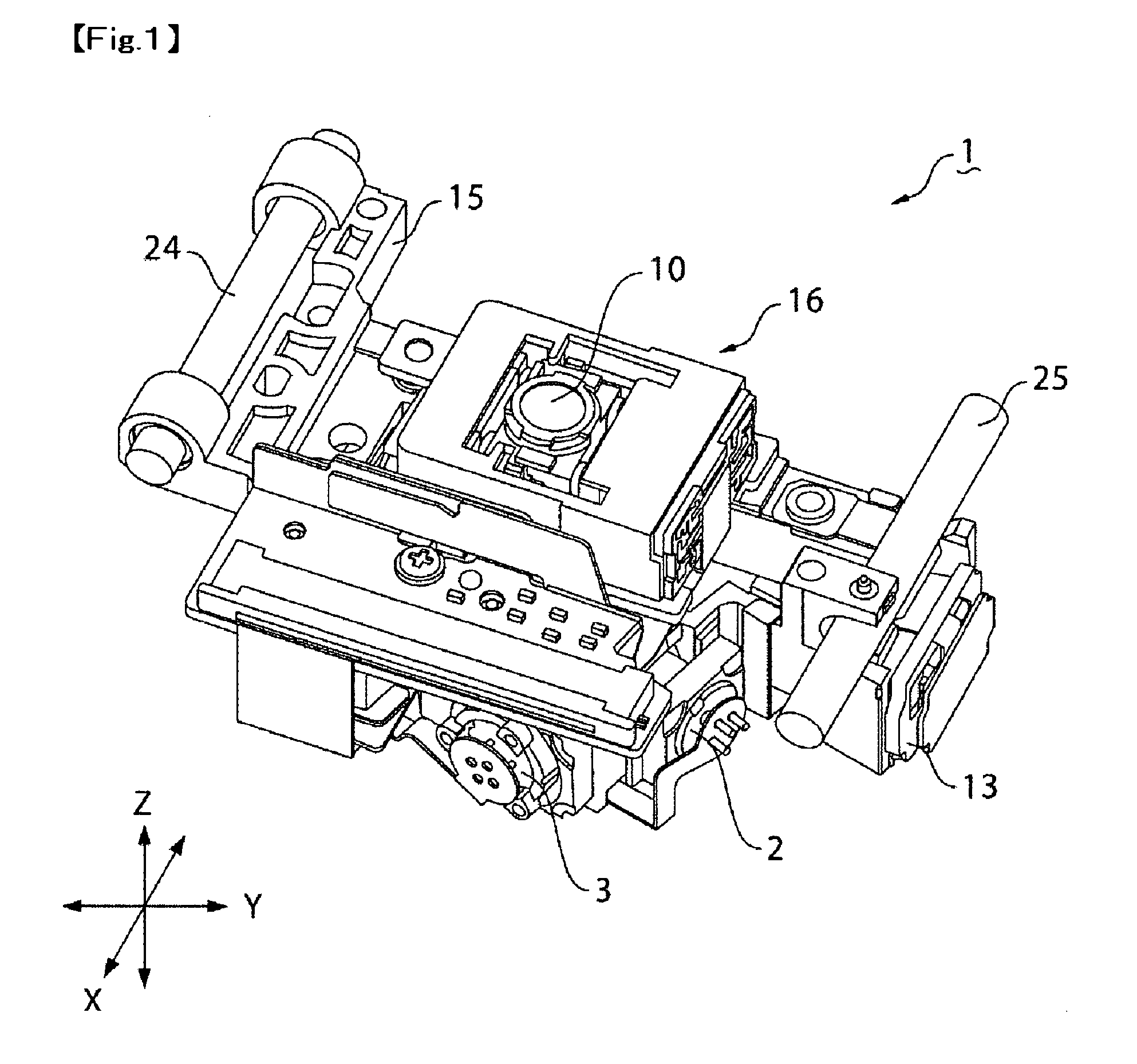
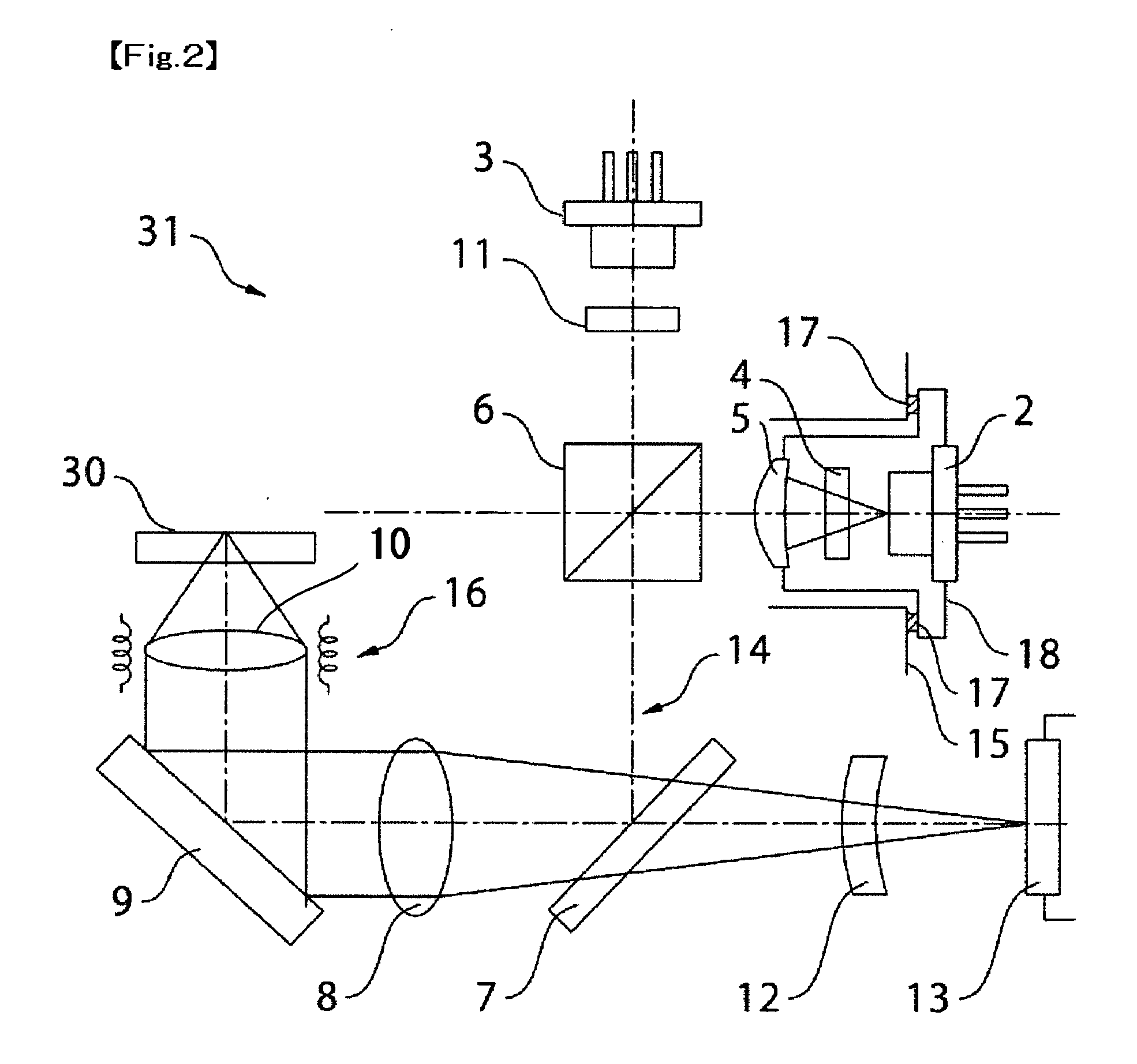
[0023]FIG. 1 is a perspective view showing an optical head device in accordance with an embodiment which is viewed from obliquely above. FIG. 2 is an explanatory view showing the structure of an optical system in the optical head device shown in FIG. 1. FIG. 3 is a bottom view showing the optical head device shown in FIG. 1, in which the cover of the optical head device is detached. FIG. 4 is a side view showing a side face in the tracking direction of the optical head device shown in FIG. 1. FIG. 5 is a bottom view showing the bottom face of the optical head device which is shown in FIG. 1.

[0024] An optical head device 1 in accordance with an embodiment performs reproducing or recording information from or on an optical disk 30 such as a CD or a DVD, and is provided with a frame 15 on which an optical system 31 and the like, w...


PUM


Abstract

An optical head device, for use with an optical disk, may include a laser beam emitting element, a light receiving element for receiving a reflected light beam emitted from the laser beam emitting element and reflected by the optical disk, a frame on which the laser beam emitting element and the light receiving element are mounted, and an adhesive which contains heat-conductive fillers having superior thermal conductivity to adhesively fix the laser beam emitting element or the light receiving element to the frame. The adhesive may be preferably a photo-curing type of adhesive which contains heat-conductive fillers and is also capable of being cured by applying heat.

Description

CROSS REFERENCE TO RELATED APPLICATION [0001] The present invention claims priority under 35 U.S.C. §119 to Japanese Application No. 2005-123127 filed Apr. 21, 2005, which is incorporated herein by reference. FIELD OF THE INVENTION [0002] An embodiment of the present invention may relate to an optical head device which is used to record or reproduce information on or from an optical disk such as a CD or a DVD and may relate to a manufacturing method for the optical head device. More specifically, an embodiment of the present invention may relate to a heat dissipation structure for a laser beam emitting element which is provided in an optical head device and may relate to a manufacturing method for the heat dissipation structure provided in the optical head device. BACKGROUND OF THE INVENTION [0003] An optical head device which is used to record or reproduce information on or from an optical disk such as a CD or a DVD includes a laser beam emitting element as a light source and a fra...

Claims


Application Information

Patent Timeline
IPC IPC(8): G11B7/00
CPCG11B7/22
Inventor MARUMO, HIROMASATSUKIOKA, YASUYUKI
Owner SANKYO SEIKI MFG CO LTD
Why Eureka
Try Eureka