Exhaust emission purifying apparatus for engine
a technology for purifying apparatus and exhaust, which is applied in the direction of mechanical apparatus, engine components, machines/engines, etc., can solve the problems of nox not being satisfactorily reduced and eliminated, urea accumulation forms an obstruction to the flow of exhaust emission in the exhaust pipe, and the elimination rate of nox might decrease in some cases, so as to enhance the elimination rate of nox
- Summary
- Abstract
- Description
- Claims
- Application Information
AI Technical Summary
Benefits of technology
Problems solved by technology
Method used
Image
Examples
first embodiment
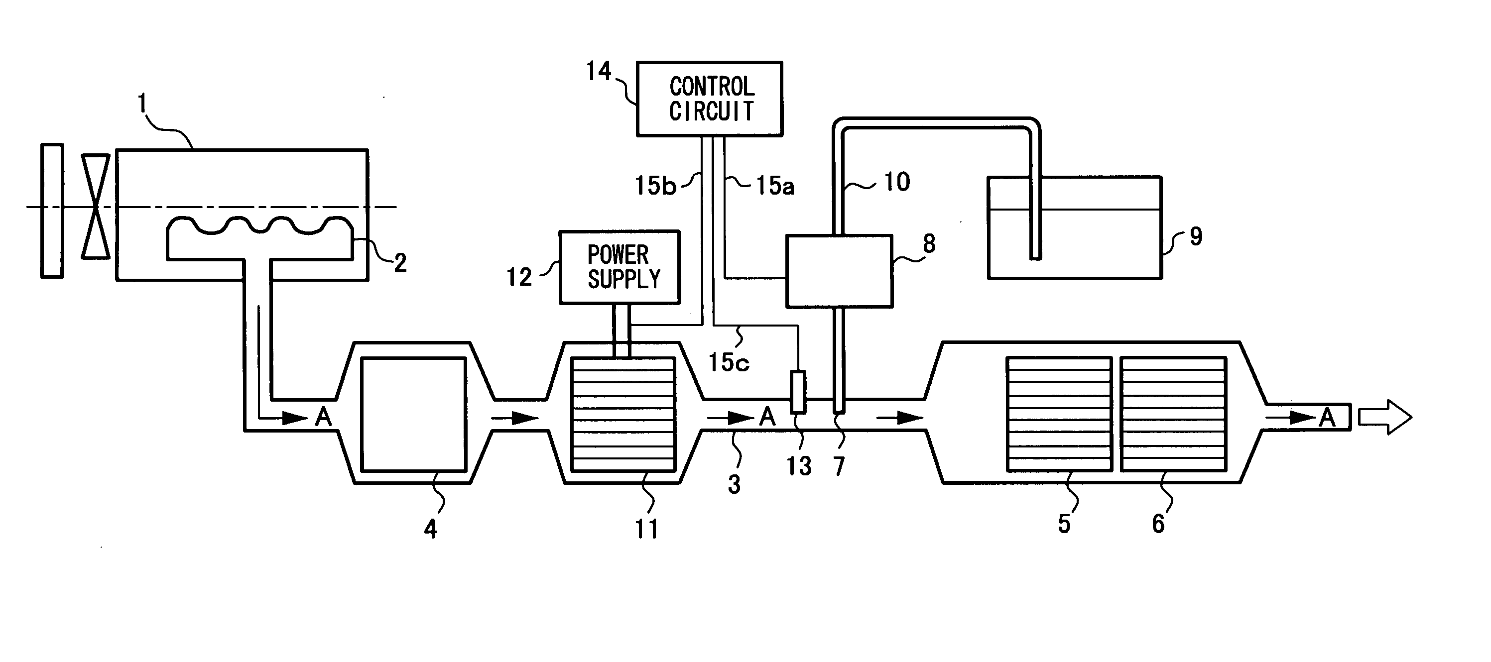
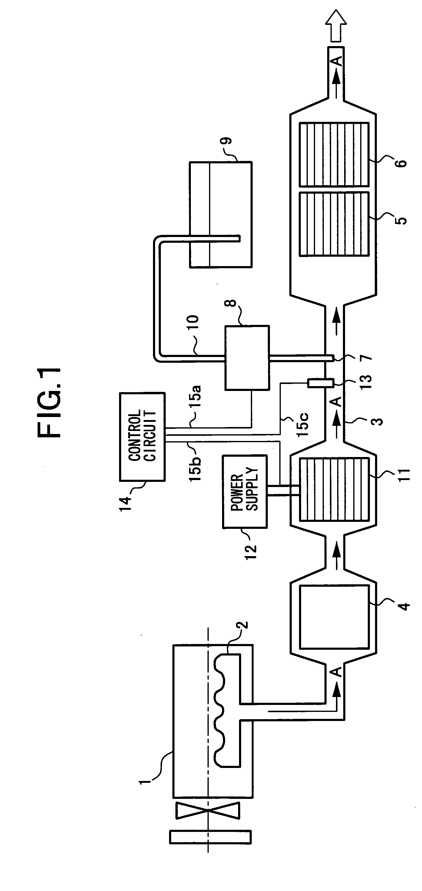
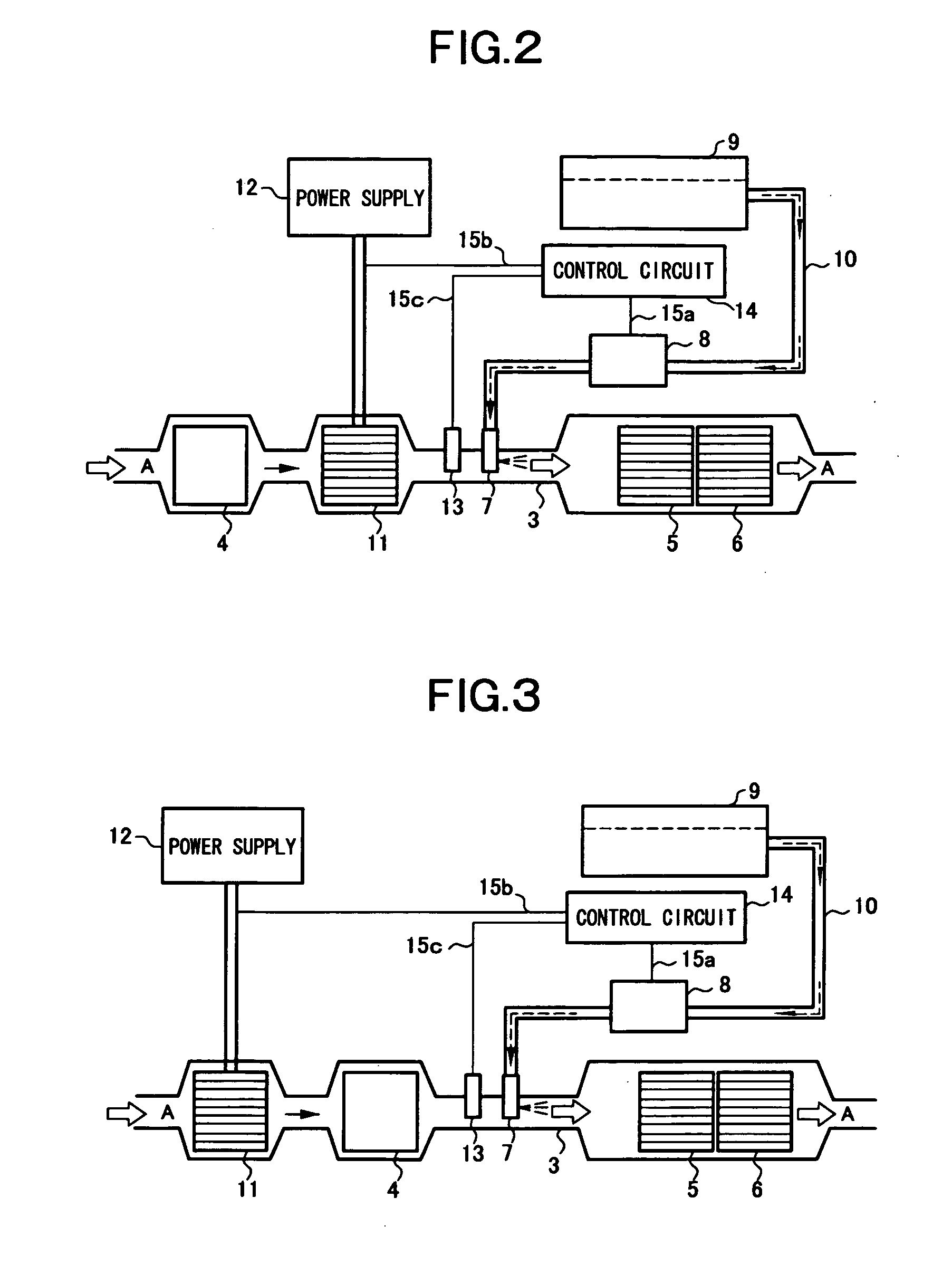
[0041]FIG. 1 shows a structure of an exhaust emission purifying apparatus for an engine according to the invention. This exhaust emission purifying apparatus reduces and eliminates NOx emitted from a diesel engine, a gasoline engine, or the like mounted on a mobile vehicle by using a reducing agent. The exhaust emission of the engine 1 using gasoline or diesel oil as fuel is emitted into the air from an exhaust pipe 3 as an exhaust passage through an exhaust manifold 2. Specifically, in the exhaust pipe 3, a nitrogen monoxide (NO) oxidation catalyst 4, a NOx reduction catalyst 5, and an ammonia slip oxidation catalyst 6 are disposed in order from an exhaust emission upstream side, and a temperature sensor, a NOx sensor and the like are disposed in front and at the rear of the catalysts to thereby form an exhaust system. However, details are not illustrated.
[0042] The oxidation catalyst 4 reduces NO and the like contained in the exhaust emission passing through the exhaust pipe 3 by ...
second embodiment
[0065] Here, in FIG. 5, a control procedure performed by the controller 24 of the exhaust emission purifying apparatus will be described. First, the controller 24 starts the control when power is supplied by turning on a power supply switch such as a key switch. The control according to the illustrated flow chart is repeatedly performed every predetermined time.
[0066] First, at step 1 (referred to as “S1” in the drawings and hereinafter the same shall apply), the outer wall temperatures T1, T3 and the exhaust emission temperatures T2, T4 are input from the first through fourth temperature sensors 17 through 20.
[0067] At step S2, the first subtracter 21 subtracts the outer wall temperature T1 from the exhaust emission temperature T2 to obtain a temperature difference ΔTd. The processing at steps S1 and S2 using first temperature sensor 17 and the second temperature sensor 18 corresponds to a first temperature deference detecting means.
[0068] At step S3, the second subtracter 22 su...
PUM
 Abstract
Description
Claims
Application Information
 - R&D
- Intellectual Property
- Life Sciences
- Materials
- Tech Scout
- Unparalleled Data Quality
- Higher Quality Content
- 60% Fewer Hallucinations
Browse by: Latest US Patents, China's latest patents, Technical Efficacy Thesaurus, Application Domain, Technology Topic, Popular Technical Reports.
© 2025 PatSnap. All rights reserved.Legal|Privacy policy|Modern Slavery Act Transparency Statement|Sitemap|About US| Contact US: help@patsnap.com


