
Sealant composition comprising a gel system and a reduced amount of cement for a permeable zone downhole

a permeable zone and gel system technology, applied in the direction of sealing/packing, well accessories, chemistry apparatus and processes, etc., can solve the problems of insufficient mechanical properties to provide sufficient resistance to flow, cement does not penetrate into the porous, and many microchannels along the cement and porous rock interfa

Active Publication Date: 2006-10-19
HALLIBURTON ENERGY SERVICES INC +1
View PDF83 Cites 205 Cited by
  • Summary
  • Abstract
  • Description
  • Claims
  • Application Information

AI Technical Summary

Problems solved by technology

Unfortunately, cement has limitations as it does not penetrate into the porous rock, but rather fills and plugs voids, perforations, etc. as noted previously.
As a result, microchannels along the cement and porous rock interface often develop due to cyclical changes in underground pressures and temperatures during subsequent production and shut-in stages.
A limitation of gels is that they may not have the mechanical properties to provide sufficient resistance to flow in the absence of a porous medium, for example in areas such as voids and cavities behind pipe.
A disadvantage of the sequential combination treatment may be that the depth of polymer invasion in the porous media extends beyond the depths that can be penetrated by perforating guns and consequently the shut-off may be permanent.
However, due to the alkalinity of the cement, which typically has a pH greater than 12, the gel time of the cement composition at the relatively high temperatures in the wellbore may be unacceptably short.

Method used


Image

  • Sealant composition comprising a gel system and a reduced amount of cement for a permeable zone downhole
  • Sealant composition comprising a gel system and a reduced amount of cement for a permeable zone downhole
  • Sealant composition comprising a gel system and a reduced amount of cement for a permeable zone downhole

Examples


example 1

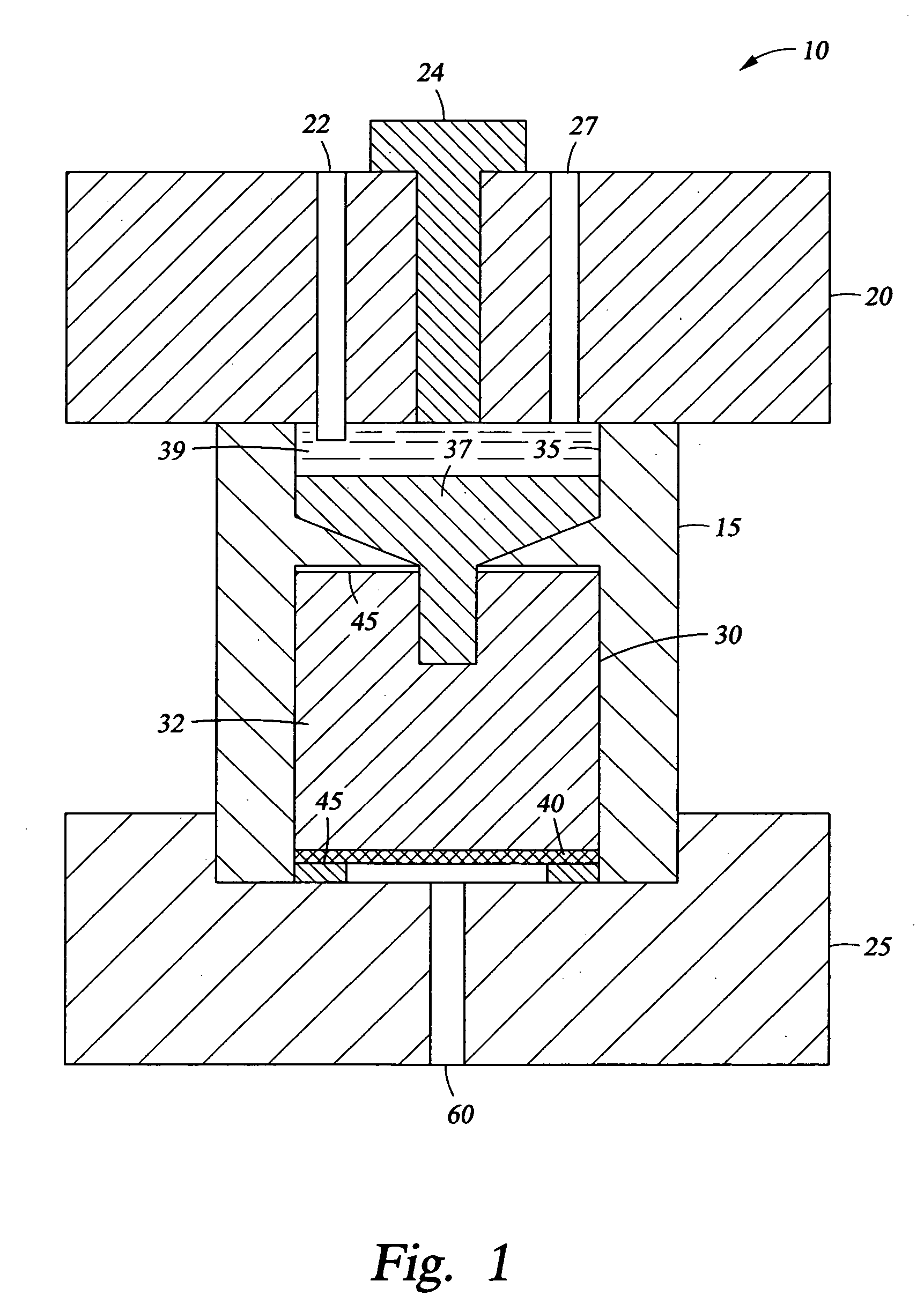
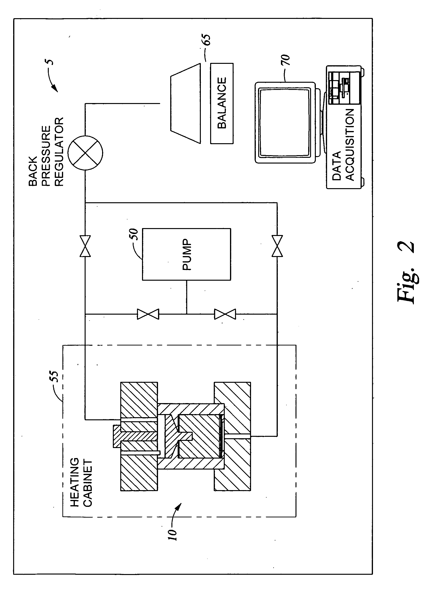
[0145] The fluid leak off properties were measured in a custom built system 5 as depicted in FIGS. 1 and 2. The stainless steel cell 10 has a body 15 disposed between an upper housing 20 and a lower housing 25. The upper housing has a temperature sensor 22, a fill port 24, and a pressure port 27. The body 15 has a central chamber 30 holding a sample of core sample 32 on top of a metal filter 40. The core sample 32 simulates the permeability of a downhole formation. Rubber seals 45 provide a seal between the core sample 32 and the upper housing 20 and lower housing 25. A fluid reservoir 35 containing a sealant composition 37 and a liquid 39 is disposed above the core sample 32. The sealant composition 37 is placed in the reservoir 35 via fill port 24, followed by the liquid 39. The liquid 39 is pressurized via pressure port 27 using pump 50, as shown in FIG. 2. The steel cell 10 may be place in a heating cabinet 55, and the combination of heat and pressure provided by heating cabinet...

example 2

[0148] Leakoff tests were performed at 120° F. using a Hassler sleeve apparatus containing a sandstone core. Brine containing 9% NaCl and 1% CaCl2 was first pumped through the core to determine the initial permeability. In a control test, a mixture of 5% polyacrylamide and 1.3% polyethylene imine in fresh water was next pumped into the core. Approximately 140 mL of this mixture was pumped through the core in 20 minutes at a differential pressure of 7 psi. This type of polymer solution offers essentially no resistance to flow through such cores. Thus, if the differential pressure had been increased, the same volume would have flowed through in a much shorter time period.

[0149] A second test utilized a mixture of 5% polyacrylamide and 1.3% polyethylene imine in fresh water, but also contained 50% by weight of 100 mesh sand. In this test a differential pressure of 1000 psi was applied, and only ˜11 mL of fluid leaked off through the core in 30 minutes. Thus, the inert filler greatly l...


PUM


Abstract

A sealant composition for servicing a wellbore comprising at least one gel system, a leak off prevention material and water.

Description

CROSS-REFERENCE TO RELATED APPLICATIONS [0001] This application is a Continuation-In-Part of copending U.S. patent application Ser. No. 11 / 041,577 filed Jan. 24, 2005 and entitled “Methods of Plugging a Permeable Zone Downhole Using a Sealant Composition Comprising a Crosslinkable Material and a Reduced Amount of Cement” and Ser. No. 11 / 041,554 filed Jan. 24, 2005 and entitled “A Sealant Composition Comprising a Crosslinkable Material and a Reduced Amount of Cement for a Permeable Zone Downhole,” which are incorporated herein by reference in their entirety. The present application also claims priority to U.S. Provisional Application Ser. No. 60 / 752,132 filed Dec. 20, 2005 and entitled “A Sealant Composition Comprising a Gel System and a Reduced Amount of Cement for a Permeable Zone Downhole,” which is incorporated by reference.FIELD OF THE INVENTION [0002] The present invention generally relates to subterranean zonal isolation, and more particularly to methods of plugging a permeabl...

Claims


Application Information

Patent Timeline
IPC IPC(8): C09K8/508
CPCC09K8/428C09K8/44C09K8/46C09K8/512C09K8/504C09K8/506C09K8/508C09K8/467
Inventor DALRYMPLE, ELDON D.EOFF, LARRY S.VAN BATENBURG, DIEDERIK W.VAN EIJDEN, JIP
Owner HALLIBURTON ENERGY SERVICES INC
Learn More