
Multithreaded processor architecture with operational latency hiding

a processor and multi-threaded technology, applied in multi-programming arrangements, instruments, computation using denominational number representations, etc., can solve the problems of substantial latency, time delay of operation, delay of operation, etc., and achieve high concurrency and latency. , the effect of hiding the latency

Active Publication Date: 2006-10-12
IBM CORP
View PDF25 Cites 44 Cited by
  • Summary
  • Abstract
  • Description
  • Claims
  • Application Information

AI Technical Summary

Benefits of technology

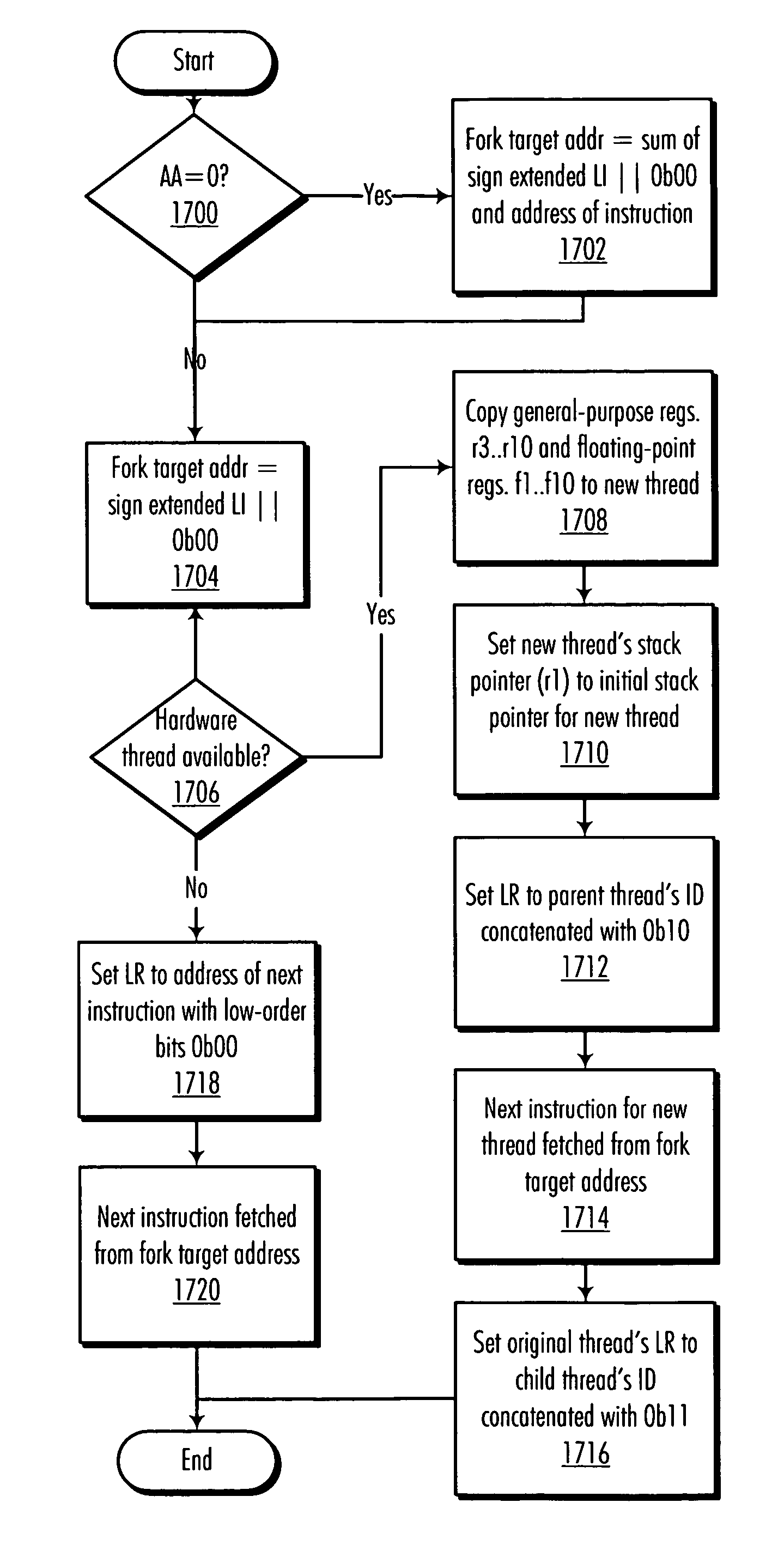
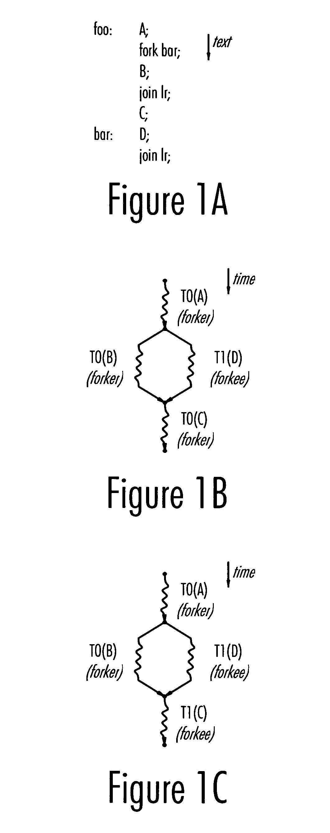
[0017] The present invention provides a method and processor architecture for achieving a high level of concurrency and latency hiding in an “infinite-thread processor architecture” with a limited number of hardware threads. A preferred embodiment defines “fork” and “join” instructions for spawning new context-switched threads. Context switching is used to hide the latency of both memory-access operations (i.e., loads and stores) and arithmetic / logical operations. When an operation executing in a thread incurs a latency having the potential to delay the instruction pipeline, the latency is hidden by performing a context switch to a different thread. When the result of the operation becomes available, a context switch back to that thread is performed to allow the thread to continue.

Problems solved by technology

However, the judge will only conduct a hearing on a single case at a time.
The latency of an operation is the time delay between when the operation is initiated and when a result of the operation becomes available.
Thus, in the case of a memory-read operation, the latency is the delay between the initiation of the read and the availability of the data.
In certain circumstances, such as a cache miss, this latency can be substantial.
SMT, however, is very complex and power-consuming.
However, other operations, such as arithmetic operations, for example, still impose a substantial performance penalty due to the latencies of the different functional units used to perform those operations.

Method used


Image

  • Multithreaded processor architecture with operational latency hiding
  • Multithreaded processor architecture with operational latency hiding
  • Multithreaded processor architecture with operational latency hiding

Examples


Embodiment Construction

[0046] The following is intended to provide a detailed description of an example of the invention and should not be taken to be limiting of the invention itself. Rather, any number of variations may fall within the scope of the invention, which is defined in the claims following the description.

[0047] The present invention provides a multithreaded processor architecture that aims at simplifying the programming of concurrent activities for memory latency hiding and parallel processing without sacrificing performance. We assume that the programmer, potentially supported by a compiler, specifies concurrent activities in the program. We call each of the concurrent activities a thread.

[0048] To date, the primary focus in the design of high-performance parallel programs is thread granularity. We denote as granularity the number of instructions shepherded by a thread during execution. Coarse granularity typically implies relatively few parallel threads, which enjoy a relatively low bookk...


PUM


Abstract

A method and processor architecture for achieving a high level of concurrency and latency hiding in an “infinite-thread processor architecture” with a limited number of hardware threads is disclosed. A preferred embodiment defines “fork” and “join” instructions for spawning new context-switched threads. Context switching is used to hide the latency of both memory-access operations (i.e., loads and stores) and arithmetic / logical operations. When an operation executing in a thread incurs a latency having the potential to delay the instruction pipeline, the latency is hidden by performing a context switch to a different thread. When the result of the operation becomes available, a context switch back to that thread is performed to allow the thread to continue.

Description

CROSS-REFERENCE TO RELATED APPLICATION(S) [0001] The present application is related to a U.S. Patent Application entitled “Multithreaded Processor Architecture with Implicit Granularity Adaptation,” Ser. No. ______, Attorney Docket No. AUS920040821US1, which is filed even date hereof, assigned to the same assignee, and incorporated herein by reference in its entirety.STATEMENT OF GOVERNMENT FUNDING [0002] This invention was made with Government support under PERCS II, NBCH3039004. THE GOVERNMENT HAS CERTAIN RIGHTS IN THIS INVENTION.BACKGROUND OF THE INVENTION [0003] 1. Technical Field [0004] The present invention relates generally to advanced computer architectures. More specifically, the present invention provides a multithreaded processor architecture that aims at simplifying the programming of concurrent activities for memory latency hiding and multiprocessing without sacrificing performance. [0005] 2. Description of the Related Art [0006] Multithreaded architectures (also referr...

Claims


Application Information

Patent Timeline
IPC IPC(8): G06F9/46
CPCG06F9/30043G06F9/3009G06F9/30112G06F9/3017G06F9/3824G06F9/38G06F9/3851G06F9/461G06F9/4843G06F11/2094G06F9/383G06F9/3854
Inventor FRIGO, MATTEOGHEITH, AHMEDSTRUMPEN, VOLKER
Owner IBM CORP
Learn More