
Spindle motor with flexible circuit board and disk drive including the same

Inactive Publication Date: 2006-10-12
NIDEC CORP
View PDF2 Cites 19 Cited by
  • Summary
  • Abstract
  • Description
  • Claims
  • Application Information

AI Technical Summary

Benefits of technology

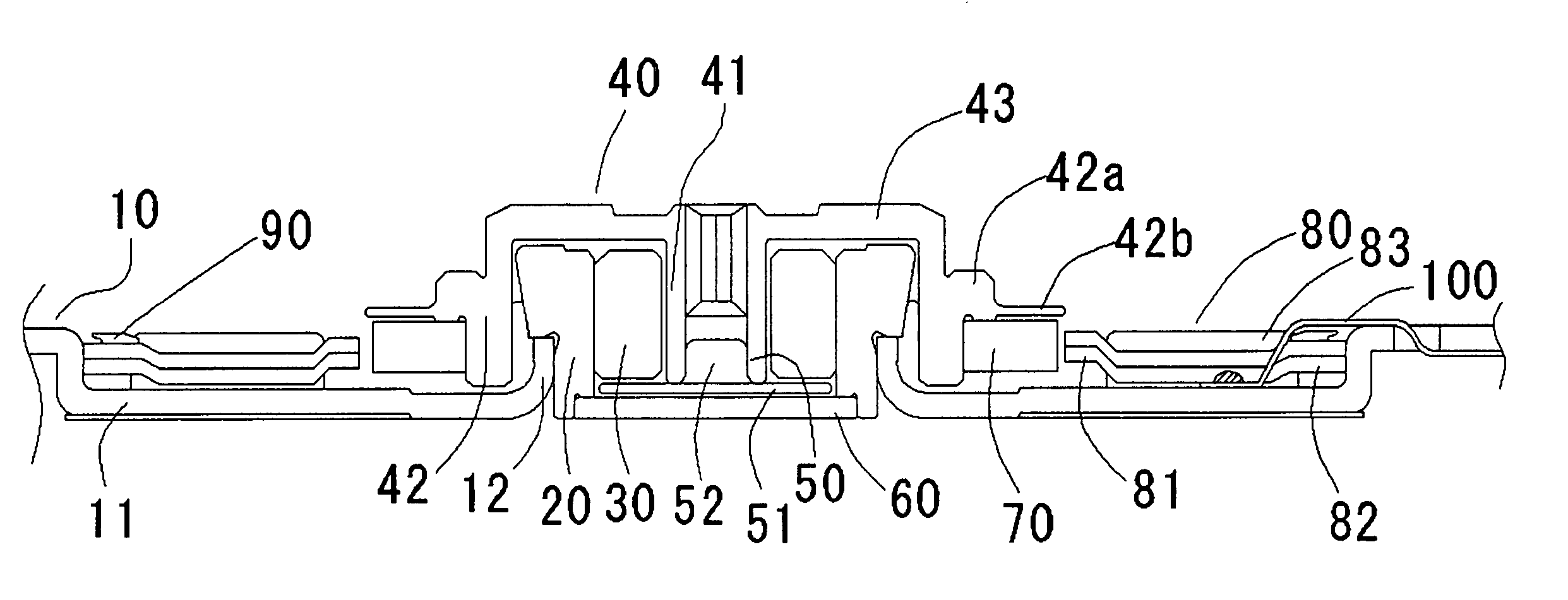
[0008] The object of this invention is to provide a spindle motor of inner rotor type in which the FPC arranged on the upper surface of the stator can be effectively fixed. A spindle motor reduced in thickness can be thus provided in which FPC is not raised even in the case where at least the magnetic shield plate of the movable part of the magnetic head of HDD is removed.
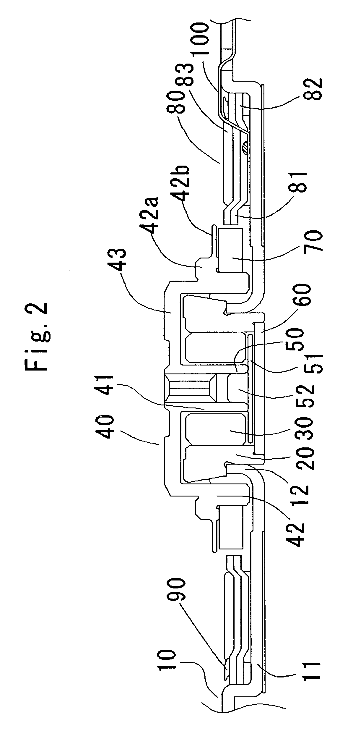
[0010] In this configuration, the FPC connecting portions are arranged between the teeth and bent down to be located axially downward of the stator. In this way, the connecting portions which have so far been arranged between the teeth to reduce the thickness as far as possible and therefore difficult to fix can easily fixed and held. As a result, the motor can be reduced in thickness while at the same time fixing the FPC, or especially, the connecting portions. Further, the connecting portions being arranged under the stator are held between the coils and thus can be held under the stator. The FPC, therefore, is kept immovable against vibrations or shocks from outside the motor, and the breakage of the coil lead which otherwise might be caused by the movement of the connecting portions is prevented.
[0012] In a miniature motor not more than 1 inch, the rotary torque is so small that the magnetic force of the rotor magnet can be small. This reduces the magnetic flux leakage between the rotor magnet and the stator opposed thereto. As long as the distance from the upper surface of the stator to the surface on which the recording disk is mounted is not less than 0.2 mm, therefore, the recording disk is not fatally affected. As a result, the magnetic shield plate which has conventionally be required to prevent the leakage of magnetism can be removed.

Problems solved by technology

Removal of the magnetic shield plate to hold the FPC height, however, would inconveniently make it difficult to successfully fix the FPC, with the result that the motor as a whole cannot be reduced in thickness.

Method used


Image

  • Spindle motor with flexible circuit board and disk drive including the same
  • Spindle motor with flexible circuit board and disk drive including the same
  • Spindle motor with flexible circuit board and disk drive including the same

Examples


Embodiment Construction

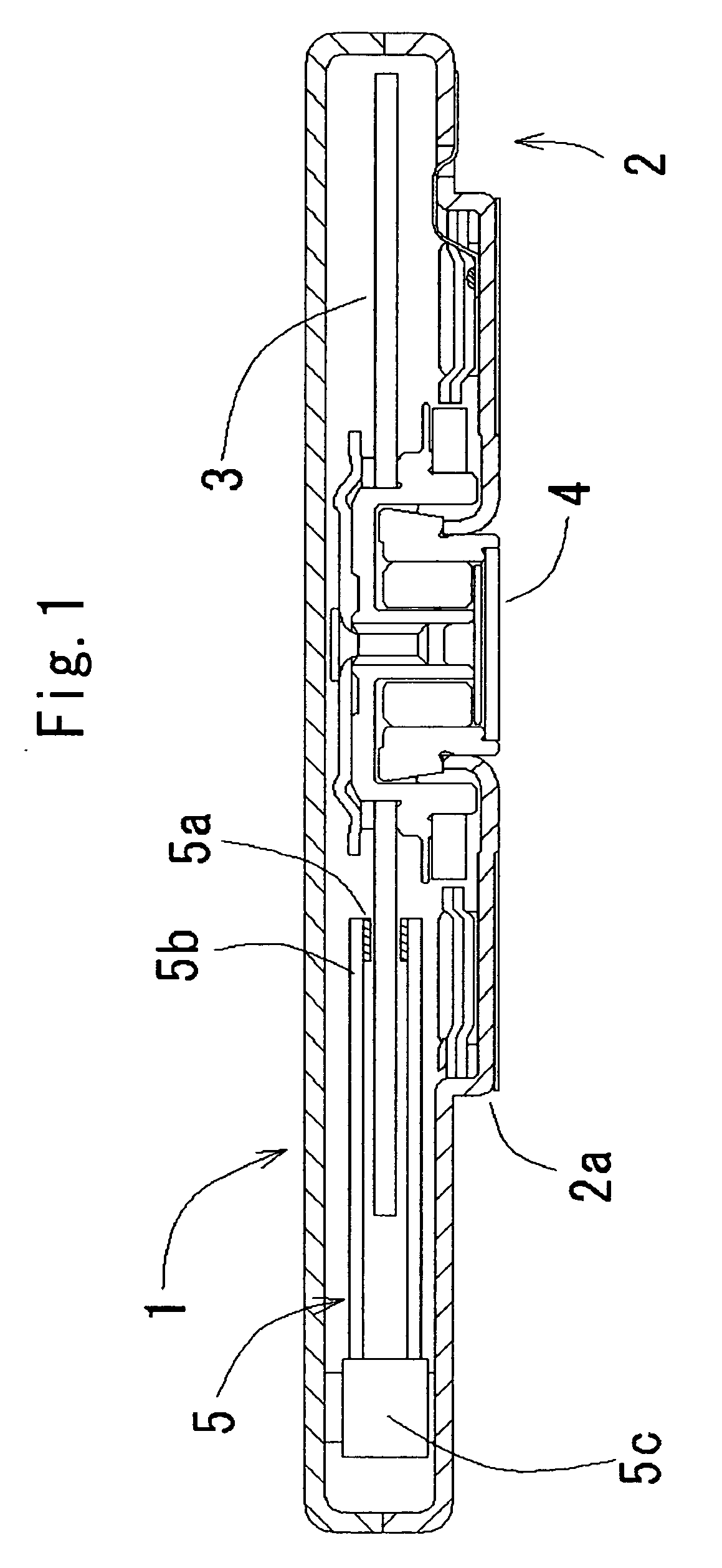
[0022]FIG. 1 shows a recording disk drive according to a first embodiment of the invention. A recording disk drive 1 has an outer housing configured of a substantially rectangular thin, flat box-like case 2. The interior of the case 2 forms a clean space substantially free of dust and dirt. The case 2 includes a lower case portion 2a and an upper case portion 2b, and an annular depression is formed on the bottom of the lower case portion 2a. A spindle motor 4 for rotationally driving a circular hard disk 3 making up an information recording medium is arranged in the annular depression. According to this embodiment, the lower case portion 2a of the case makes up a base member of the spindle motor 4. Alternatively, however, a base member independent of the case 2 may be mounted on the case 2.

[0023] A head moving mechanism 5 for reading and writing data in the hard disk 3 is arranged in the case 2. This head moving mechanism 5 includes a magnetic head 5a for reading and writing inform...


PUM


Abstract

A spindle motor for rotating a recording disk such as a magnetic disk is disclosed. The stator coil of the spindle motor is connected to an external device using a FPC including an outer frame located on the upper surface of a circular core back of the stator core and a plurality of connecting portions formed continuously in radial direction inward from the outer frame each with a land connected with a each coil end between adjacent ones of the teeth of the stator core. Each connecting portion is bent down from the outer frame and arranged under the stator. The FPC connecting portions are each arranged between the teeth and bent down axially under the stator. In this way, the FPC connecting portions can be easily held fixedly to reduce the thickness of the motor.

Description

BACKGROUND OF THE INVENTION [0001] 1. Field of the Invention [0002] This invention relates to a spindle motor of inner rotor type for supplying a current to the stator coil using a flexible printed circuit board (FPC) to rotationally drive a recording disk, for example, or in particular to a thin, compact spindle motor suitably used for rotationally driving a recording disk not more than one inch in outer diameter, and a recording disk drive having the spindle motor mounted thereon. [0003] 2. Description of the Related Art [0004] A recording disk drive, or especially, a hard disk drive (HDD) mounted for use on a portable music player or a portable device such as a mobile phone is required to be thin and compact. In mounting the HDD on a mobile phone, in particular, the outer diameter of the HDD disk not more than 1 inch is essential, in which case the axial height of the spindle motor built in the HDD is required is several mm. Though difficult to further reduce the thickness greatl...

Claims


Application Information

Patent Timeline
IPC IPC(8): G11B17/02
CPCG11B19/2009H02K3/522H02K2203/03H02K11/0073H02K5/225H02K11/33
Inventor TAMAOKA, TAKEHITOMATSUDA, KAZUAKI
Owner NIDEC CORP
Learn More