
Tubular reaction vessel and process for producing silicon therewith

a reaction vessel and tube technology, applied in the direction of crystal growth process, silicon compound, transportation and packaging, etc., can solve the problems of reducing the yield of silicon, the process is complicated, and the heat cannot penetrate the filler layer deep, so as to reduce the upward flow and improve efficiency. , the effect of uniform heating

Active Publication Date: 2006-10-05
TOKUYAMA CORP
View PDF5 Cites 8 Cited by
  • Summary
  • Abstract
  • Description
  • Claims
  • Application Information

AI Technical Summary

Benefits of technology

[0022] The invention enables effective reduction of the upward flow by causing it to contact with the flow resistance-increasing region on the internal wall of the tubular reaction vessel to change the flow direction. The flow resistance-increasing region also allows for effective mixing of the feedstock gas with the upward flow in the vicinity of the central axis of the tubular reaction vessel.
[0023] Consequently, the upward flow acting as a boundary layer is eliminated, and the feedstock gas can contact with the internal wall of the tubular reaction vessel with improved efficiency and can be heated uniformly. Furthermore, the feedstock gas can be effectively contacted with the deposition surface and, even when silicon fine powder is generated, the fine powder is recontacted with the deposited silicon surface and is incorporated therein, in addition, the feedstock gas can be heated uniformly to a high temperature, so that the silane oligomer generated can be redecomposed, thereby, the by-products discharged from the reaction vessel can be dramatically reduced. Thus, improvement of the reaction efficiency and prevention of by-products can be achieved.PREFERRED EMBODIMENTS OF THE INVENTION
[0024] Hereinbelow, representative embodiments of the present invention will be described with reference to the attached drawings. However, the invention is not limited to the illustrated embodiments.
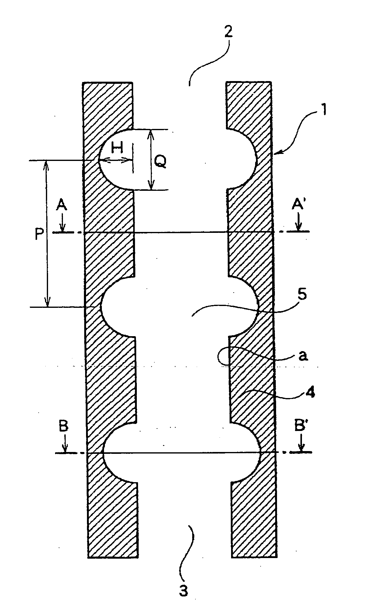
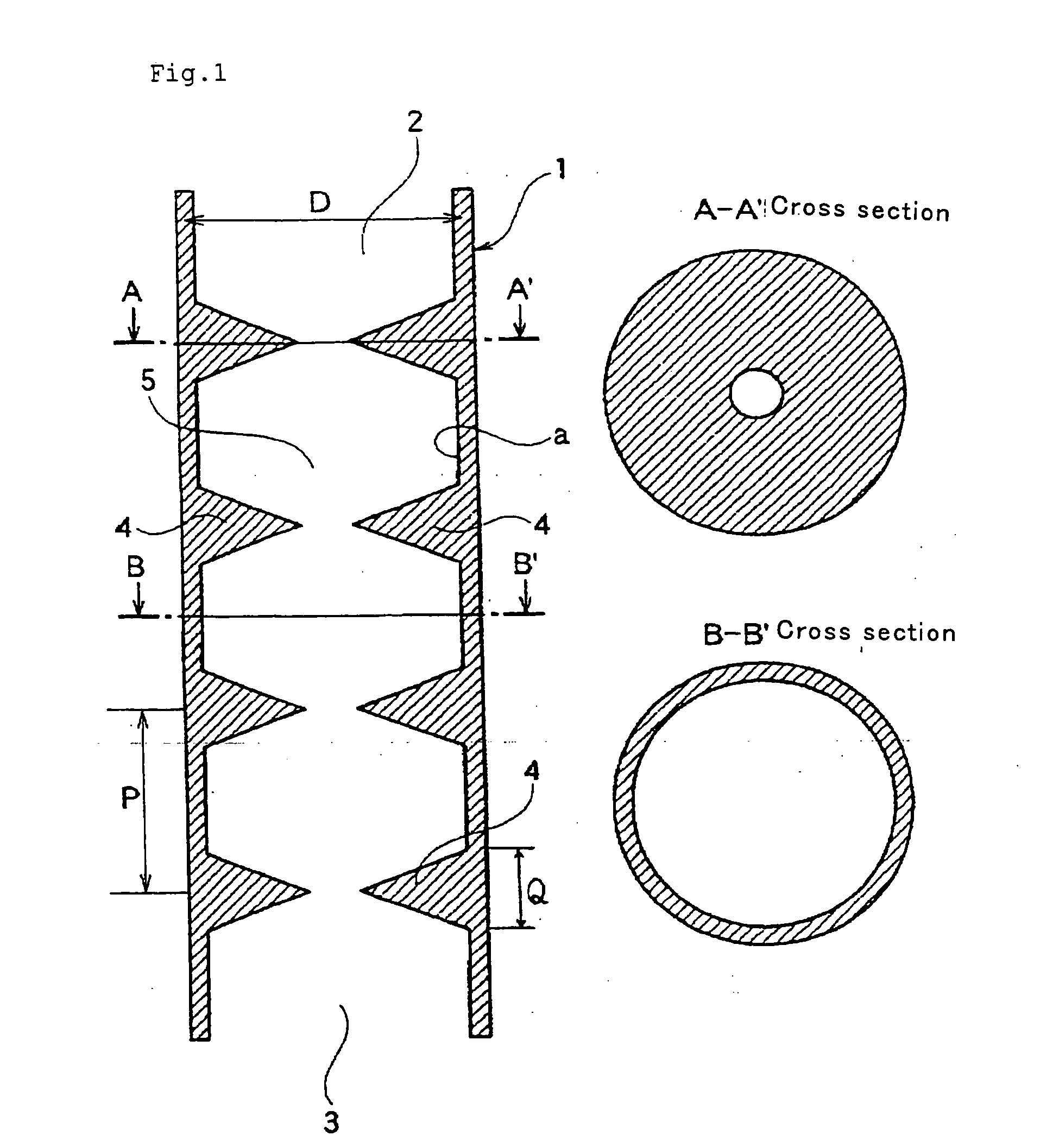
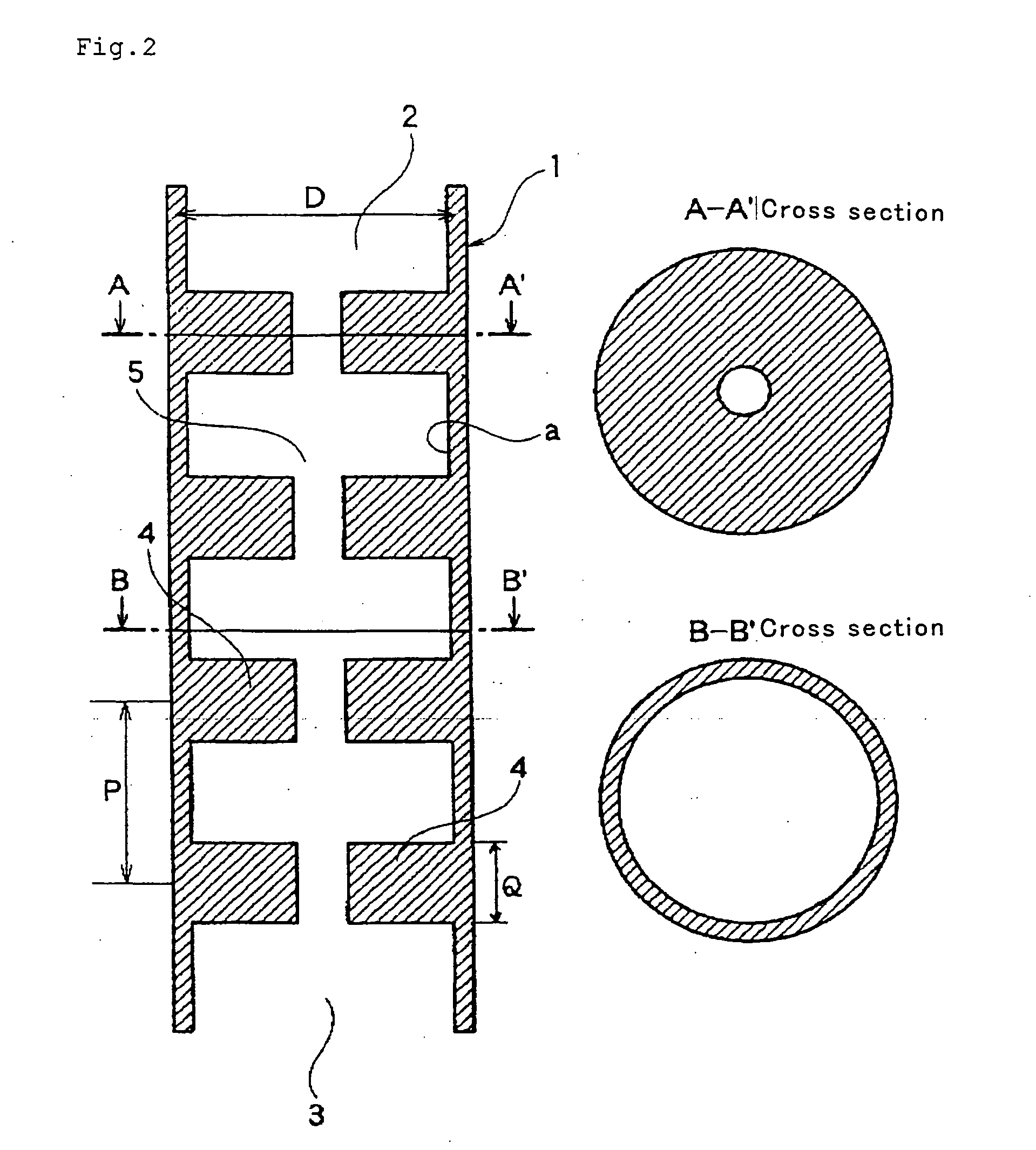
[0025] FIGS. 1 to 16 are schematic views illustrating embodiments of tubular reaction vessels according to the present invention.
[0026]FIG. 1 is a schematic sectional view of a basic embodiment of a tubular reaction vessel according to the present invention. (FIG. 1 is a vertical sectional view of the tubular reaction vessel.)
[0027] In FIG. 1, the numeral 1 denotes a tubular reaction vessel, 2 denotes a silicon deposition feedstock gas inflow opening, 3 denotes a deposited silicon discharge opening, 4 denotes a flow resistance increasing region, and 5 denotes a space through which the silicon deposition feedstock gas is passed. The tubular reaction vessel 1 shown in FIG. 1 has the silicon deposition feedstock gas inflow opening 2 and the deposited silicon discharge opening 3, and is provided with the flow resistance-increasing regions 4 on a wall surface with which the feedstock gas is contacted. In the figure, the section along the line A-A′ is of an area formed with the flow resistance-increasing region at a right angle to the longitudinal direction; the section along the line B-B′ is of an area without the flow resistance-increasing region.

Problems solved by technology

Because of batchwise deposition, however, the process has a problem of a very complicated procedure including placement of the silicon rod as a seedbed, energization heating, deposition, cooling and takeout of the silicon rod, as well as bell jar washing.
Furthermore, the scale-up tends to increase the probability of generation of by-products such as silicon fine powder and silane oligomers, resulting in lower silicon yields.
Moreover, the by-products often adhere to a reaction gas discharge line to cause blockage.
However, the following problem is often encountered.
The silicon deposition reaction vessel is generally heated inside by heat conduction from external heating means, and therefore heat cannot reach deep into the filler layer.
As a result, a great temperature difference is caused within the filler layer between the vicinity of the reaction vessel wall and the vicinity of the filler layer central axis.
Sufficient heating to the vicinity of the central axis is particularly difficult with a scaled-up large diameter reaction vessel, even with the use of heating means such as a high-frequency induction heating system or a dielectric heating system which relatively facilitates deep heating, and then, ultimately, a solid deposit clogs the filler layer.
When the heating output is increased to solve the above problem, a vicinity of the heating means, for example the external wall of the reaction vessel, is heated to an extremely high temperature, so that the reaction vessel material is remarkably deteriorated, leading to a new problem such as difficult long-term operation.

Method used


Image

  • Tubular reaction vessel and process for producing silicon therewith
  • Tubular reaction vessel and process for producing silicon therewith
  • Tubular reaction vessel and process for producing silicon therewith

Examples


example 1

[0124] The following description will be presented with reference to a schematic view of FIG. 22.

[0125] A tubular reaction vessel 41 made of general-purpose isotropic graphite was provided, which was cylindrical and straight in a longitudinal direction and had an inner diameter of 150 mm, a reaction section length I of 600 mm and a thickness of 15 mm. Heating means 43 was a high frequency heating system. The high frequency heating coil as the heating means 43 for the reaction section I extended along the reaction section I of the tubular reaction vessel 41 to a length of 100 mm from each of the upper and lower ends of the reaction section I. The frequency of the high frequency heating means was 8 kHz. A 50 mm thick carbon fiber heat insulator was arranged between the reaction vessel 41 and the heating means 43, extending from 30 mm above the lower end of the reaction vessel 41 to the upper end of the heating means 43.

[0126] Flow resistance-increasing regions provided inside the tu...

example 2

[0130] The following description will be presented with reference to a schematic view of FIG. 23.

[0131] A tubular reaction vessel 51 was a vessel with a ring-shaped cross section that consisted of an outer tube 51(a) and an inner tube 51(a′) having a smaller inner diameter. The outer tube 51(a) was an isotropic graphite cylinder 250 mm in inner diameter and 5 mm in thickness. The inner tube 51(a′) was a general-purpose isotropic graphite cylinder having an inner diameter of 200 mm and a thickness of 15 mm. The reaction vessel had a straight reaction section having a length I of 1 m, and an opening 52 at a lower end.

[0132] A space 54 was created between the outer tube 51(a) and the inner tube 51(a′). A heating coil capable of generating a high frequency wave of 1 kHz was arranged as heating means 53 to heat part of the space-facing surfaces with which the feedstock gas could contact, to at least the melting point of silicon. The heating coil was arranged so as to enclose the outer ...

example 3

[0139] The following description will be presented with reference to a schematic view of FIG. 24.

[0140] A tubular reaction vessel 41 made of general-purpose isotropic graphite was provided, which was cylindrical and had an inner diameter of 210 mm, a thickness of 25 mm and a length of 4000 mm. The reaction vessel 41 included two parts: a principal reaction section IA ranging from the lower end of the reaction vessel to a height of 2800 mm, and an auxiliary reaction section IB having a length of 560 mm above the principal reaction section IA Heating means used herein were, high frequency heating systems. A high frequency heating coil 43A as the heating means for the principal reaction section IA extended from the upper end of the principal reaction section IA to 50 mm below the lower end of the reaction vessel 41. A high frequency heating coil 43B as the heating means for the auxiliary reaction section IB extended to the same height and in the same length as the auxiliary reaction s...


PUM

PropertyMeasurementUnit
Reynolds numberaaaaaaaaaa
temperatureaaaaaaaaaa
thicknessaaaaaaaaaa

Abstract

There is provided a reaction vessel whereby silicon produced can be smoothly recovered dropwise without excessive thermal load on constitutional parts of the reaction vessel, a silicon deposition feedstock gas can be reacted efficiently even when the reaction vessel is scaled up to industrial large-scale equipment, generation of silicon fine powder and silane oligomers can be suppressed, and industrial silicon production can be performed over extended periods. The tubular reaction vessel comprises a longitudinally-extending wall with a space thereinside, wherein a silicon deposition feedstock gas inflow opening and a deposited silicon discharge opening are provided at an upper portion and a lower end portion respectively, and a flow resistance-increasing region is created on a wall surface of the tubular reaction vessel that is contacted with a feedstock gas. The flow resistance-increasing region is at least one of protrudent, concave and sloped regions.

Description

FIELD OF THE INVENTION [0001] The present invention relates to a novel reaction vessel for producing silicon from a silicon deposition feedstock gas containing a chlorosilane and hydrogen. More particularly, the invention relates to a reaction vessel that permits stable and efficient silicon production over extended periods and enables reduction of by-products to an extremely low level. The invention also relates to a silicon production process using the reaction vessel. BACKGROUND OF THE INVENTION [0002] There are many known processes for producing polycrystalline silicons used as semiconductors and photovoltaic cell materials, and some processes are performed in the industry. [0003] One of such processes is the so-called Siemens process, in which a silicon rod heated by energization to a silicon deposition temperature is placed in a bell jar, and trichlorosilane (SiHCl3, hereinafter TCS) or monosilane (SiH4) together with a reducing gas such as hydrogen are brought into contact wi...

Claims


Application Information

Patent Timeline
Patent Type & Authority Applications(United States)
IPC IPC(8): C30B11/10C30B11/00B01F23/10B01J19/00B01J19/24C01B33/02C01B33/03
CPCB01F3/02Y10T117/1028B01F5/0646B01F5/0647B01F5/065B01F5/0655B01F2005/0625B01F2005/0636B01F2005/0637B01J19/0053B01J19/2415B01J19/2425B01J19/244B01J2219/00015C01B33/02C01B33/03Y10T117/10B01F5/0618B01F23/10B01F25/431971B01F25/431972B01F25/4331B01F25/433B01F25/4333B01F25/4338B01F25/43161
Inventor WAKAMATSU, SATORUSUGIMURA, SHIGEKINAKAMURA, YASUOTSUJIO, KENICHI
Owner TOKUYAMA CORP
Learn More