
Separable sheath and method for insertion of a medical device into a bodily vessel using a separable sheath

Inactive Publication Date: 2006-09-28
RUIZ CARLOS +1
View PDF18 Cites 34 Cited by
  • Summary
  • Abstract
  • Description
  • Claims
  • Application Information

AI Technical Summary

Benefits of technology

[0012] Ends of the proximal and distal portions may be connected by a magnetic force. For example, an end of at least one of the proximal and distal portions may include a magnet, e.g., an electro-magnet, configured to generate a magnetic field, and an end of the other of the proximal and distal portions may include a magnetically-attractable member, a permanent magnet, an electro-magnet, etc., which is attracted to the magnetic field. Interruption of the magnetic field eliminates the magnetic force between the proximal and distal portions of the sheath and, therefore, effectively disconnects these portions.
[0014] The splittable sheath may include a weakened section or frangible section at a predetermined location along the length of the sheath to provide that the splitting of the sheath occurs a desired predetermined location on the sheath. Pulling the proximal and distal ends of the sheath away from each other at a predetermined pulling force or twisting the ends of the sheath relative to each other at a predetermined twisting force may cause failure at the weakened or frangible section thus splitting the sheath into proximal and distal portions. The wall of the sheath may have a reduced thickness or may be cut at the weakened section so as to facilitate splitting of the sheath.

Problems solved by technology

Blood flow created by the beating of the heart and the tortuous nature of many bodily vessels increases the difficulty of such insertion.
Pulling the proximal and distal ends of the sheath away from each other at a predetermined pulling force or twisting the ends of the sheath relative to each other at a predetermined twisting force may cause failure at the weakened or frangible section thus splitting the sheath into proximal and distal portions.

Method used


Image

  • Separable sheath and method for insertion of a medical device into a bodily vessel using a separable sheath
  • Separable sheath and method for insertion of a medical device into a bodily vessel using a separable sheath
  • Separable sheath and method for insertion of a medical device into a bodily vessel using a separable sheath

Examples


Embodiment Construction

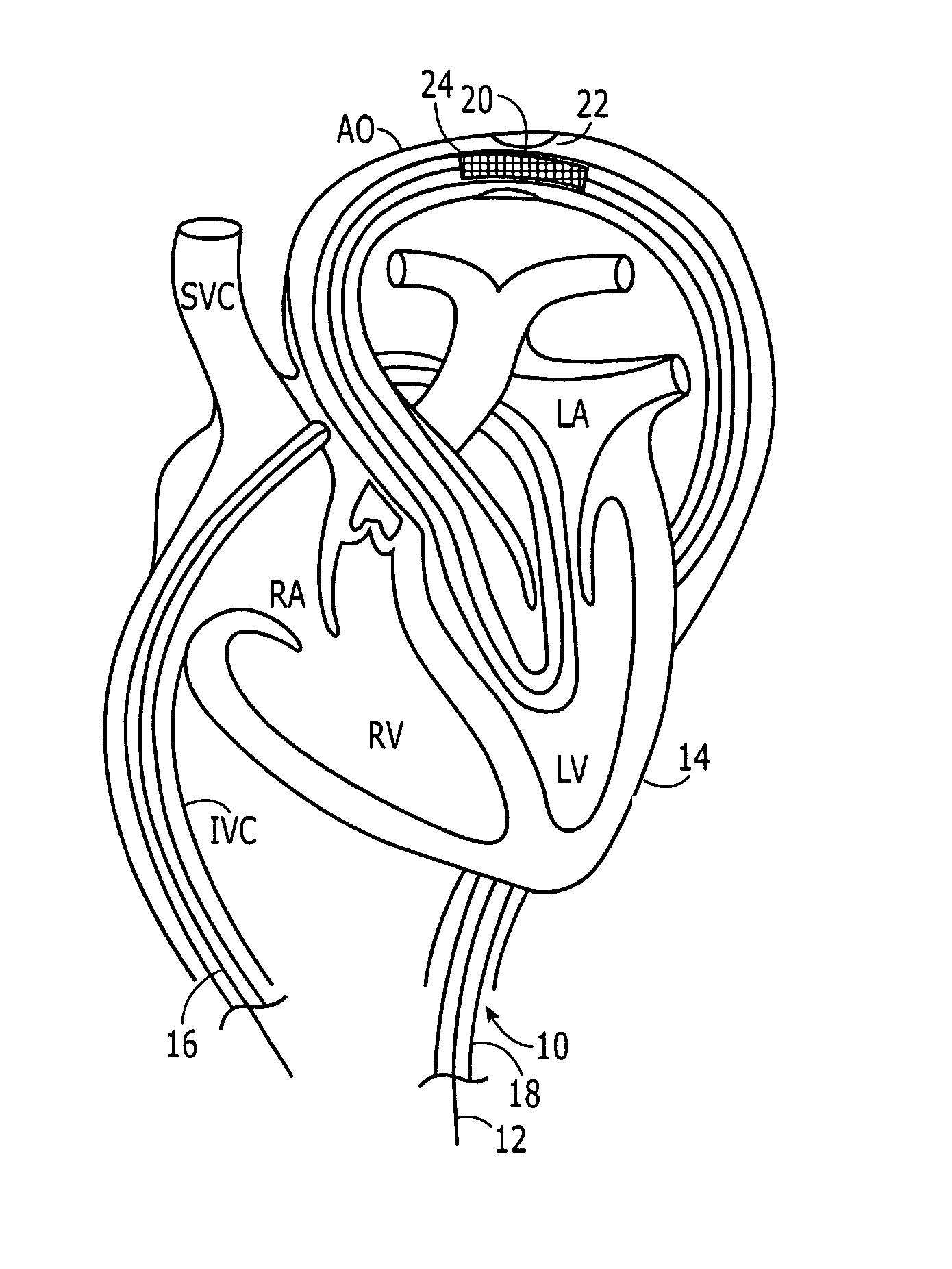
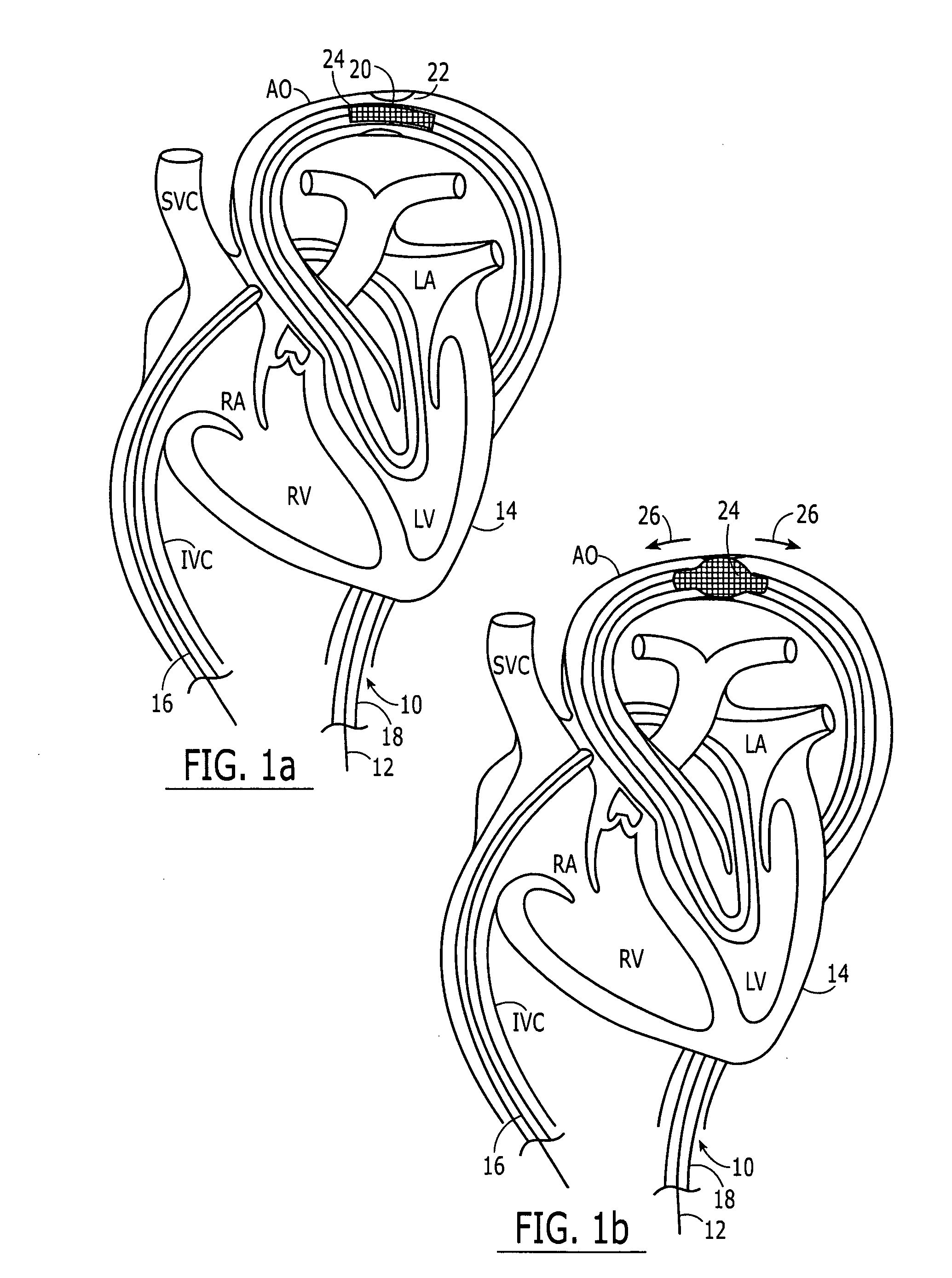
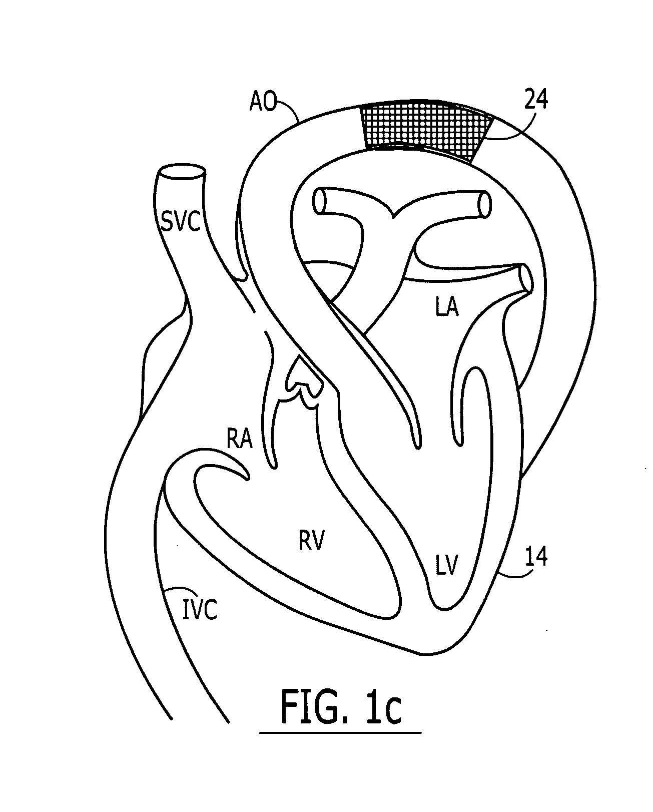
[0063]FIG. 1a illustrates an insertion sheath 10 inserted into a patient over a guidewire 12. The patient's heart 14 and vasculature are illustrates in cross-section. The guidewire 12 may be placed using any suitable guide wire insertion method. For example, the guide wire 12 may be placed using the techniques of transseptal catheterization, which includes floating a balloon catheter in the direction of blood flow through the left atrium (LA), left ventricle (LV), and into the aorta (AO), which is then retrogradely snared. In a version of a conventional technique, the insertion sheath is advanced into the left atrium (LA) using its own dilator. The dilator is pulled out and the balloon catheter is then advanced through the sheath and exteriorized in the left atrium (LA). Once in the left atrium (LA), a balloon on the balloon catheter is inflated and floated out of the left ventricle (LV) through the aortic valve into the descending aorta, across the aortic arch and into the descendi...


PUM


Abstract

A separable or splittable insertion sheath is for inserting a medical device into a patient. The insertion sheath includes releasably connectable ends or is configured to split into proximal and distal sections upon application of a predetermined level of pulling or twisting force to opposite ends of the insertion sheath. A medical device loaded into the insertion sheath is deployed by pulling the proximal and distal sections away from each other to expose the medical device.

Description

[0001] U.S. Provisional Patent Application No. 60 / 593,173, filed on Dec. 16, 2004 and entitled “Prosthetic Valve,” is expressly incorporated herein in its entirety by reference thereto. U.S. patent application Ser. No. ______, entitled “A Heart Valve and Method for Insertion of the Heart Valve Into a Bodily Vessel,” bearing Attorney Docket No. 13430 / 1, filed in the United States Patent and Trademark Office on the even date herewith is also expressly incorporated herein in its entirety by reference thereto.FIELD OF THE INVENTION [0002] The present invention relates to a separable sheath and a method for insertion of a medical device into a bodily vessel using a separable sheath. BACKGROUND INFORMATION [0003] Various methods exist for transcatheter implantation of a medical device into a bodily vessel of a patient. For example, angioplasty procedures may involve implantation of an expandable stent using a balloon catheter. The balloon catheter is typically advanced into the vasculatur...

Claims


Application Information

Patent Timeline
IPC IPC(8): A61F2/06
CPCA61F2/2412A61F2/2418A61F2/2433A61F2/97A61F2210/009A61F2220/0066A61M25/0668A61M2025/0681A61F2220/0041A61F2220/005A61F2250/0071
Inventor RUIZ, CARLOSDORROS, GERALD
Owner RUIZ CARLOS
Learn More