
Semiconductor package structure and method for manufacturing the same

Active Publication Date: 2006-09-07
ADVANCED SEMICON ENG INC
View PDF3 Cites 37 Cited by
  • Summary
  • Abstract
  • Description
  • Claims
  • Application Information

AI Technical Summary

Benefits of technology

[0009] It is an object of the present invention to provide a semiconductor package structure and a method for manufacturing the same, which can offer higher packaging efficiency and eliminate many limitations and drawbacks in the prior art.
[0011] The semiconductor package structure according to the present invention can be massively produced at the wafer level, thus reducing the cost for the package process and increasing the packaging reliability.
[0013] The semiconductor package structure and the method for manufacturing the same according to the present invention may prevent the bonding pads and the adjacent traces thereof from damage caused by the over-temperature generated during laser drilling and further prevent the chip from being disabled, owing to the fact that the via holes are formed on the scribe lines while being kept apart from the pads with an appropriate distance.

Problems solved by technology

Further, as the demands for lighter and more complex electronic devices gradually increase, the operating speed and the complexity of IC chips have become higher and higher.
However, these semiconductor package structures and the manufacturing methods in the prior art still have many limitations and drawbacks, and therefore can not entirely meet the requirements for the semiconductor package structures.

Method used


Image

  • Semiconductor package structure and method for manufacturing the same
  • Semiconductor package structure and method for manufacturing the same
  • Semiconductor package structure and method for manufacturing the same

Examples


Embodiment Construction

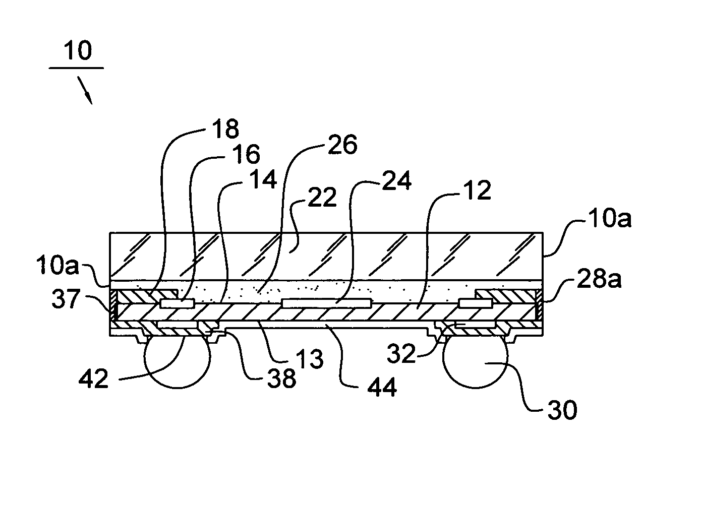
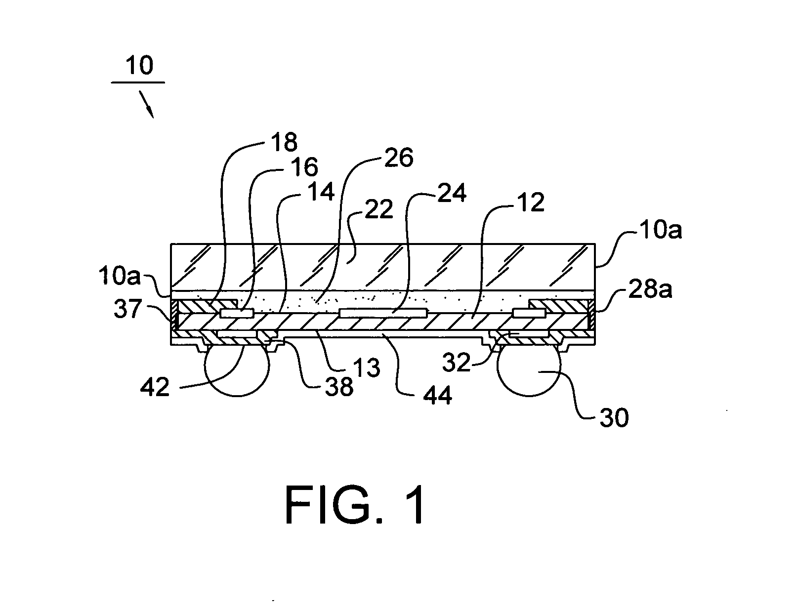
[0017] Now refer to FIG. 1, which shows a sectional view of a semiconductor package structure 10 according to a first embodiment of the present invention. The semiconductor package structure 10 comprises a chip 12 having an active surface 14, a back surface 13 opposite to the active surface 14, an optical component 24 (e.g. a sensor or a photo coupler) disposed on the active surface 14 and electrically connected to the chip 12, and a plurality of bonding pads 16 disposed on the active surface 14. The optical component 24 can be formed from complementary metal-oxide semiconductor (CMOS).

[0018] The chip 12 further has a plurality of via holes 28a, penetrating the chip 12 and exposed out of the side surface 10a of the semiconductor package structure 10, and a plurality of pad extension traces 18 for electrically connecting the bonding pads 16 to the via holes 28a. The semiconductor package structure 10 further comprises a lid 22 being adhered onto the active surface 14 of the chip 12 ...


PUM


Abstract

A semiconductor package structure comprises a chip, a plurality of pad extension traces, a plurality of via holes, a lid and a plurality of metal traces, wherein the chip has an optical component and a plurality of pads disposed on its active surface; pad extension traces are electrically connected to the pads; the via holes penetrate the chip and are electrically connected to the pad extension traces and exposed out of side surfaces of the semiconductor package structure; the lid is adhered onto the active surface of the chip; and the plurality of metal traces is disposed on the back surface of the chip, electrically connected to the plurality of via holes, and used to define a plurality of solder pads thereon. The present invention also provides a method for manufacturing the semiconductor package structure.

Description

CROSS REFERENCE TO RELATED APPLICATION [0001] This application claims the priority benefit of Taiwan Patent Application Serial Number 094106297, filed on Mar. 2, 2005, the full disclosure of which is incorporated herein by reference. BACKGROUND OF THE INVENTION [0002] 1. Field of the Invention [0003] This invention generally relates to a semiconductor package structure and a method for manufacturing the same, and more particularly to a wafer level semiconductor package structure and a method for manufacturing the same. [0004] 2. Description of the Related Art [0005] The semiconductor package mainly serves four functions, i.e. signal distribution, power distribution, heat dissipation and element protection. In general, a semiconductor chip is packaged into an enclosure, and then disposed on a printed circuit board, together with other components, such as capacitors, resistors, inductors, filters, switches, and optical and RF components. [0006] The complementary metal-oxide semiconduc...

Claims


Application Information

Patent Timeline
IPC IPC(8): H01L23/12
CPCH01L23/3114H01L27/14618H01L27/14683H01L31/0203H01L2924/0002H01L2924/00
Inventor YEE, KUO CHUNG
Owner ADVANCED SEMICON ENG INC
Learn More