
Feeding unit for engaging element metallic linear material in continuous manufacturing apparatus for fastener stringer

Active Publication Date: 2006-09-07
YKK CORP
View PDF17 Cites 5 Cited by
  • Summary
  • Abstract
  • Description
  • Claims
  • Application Information

AI Technical Summary

Benefits of technology

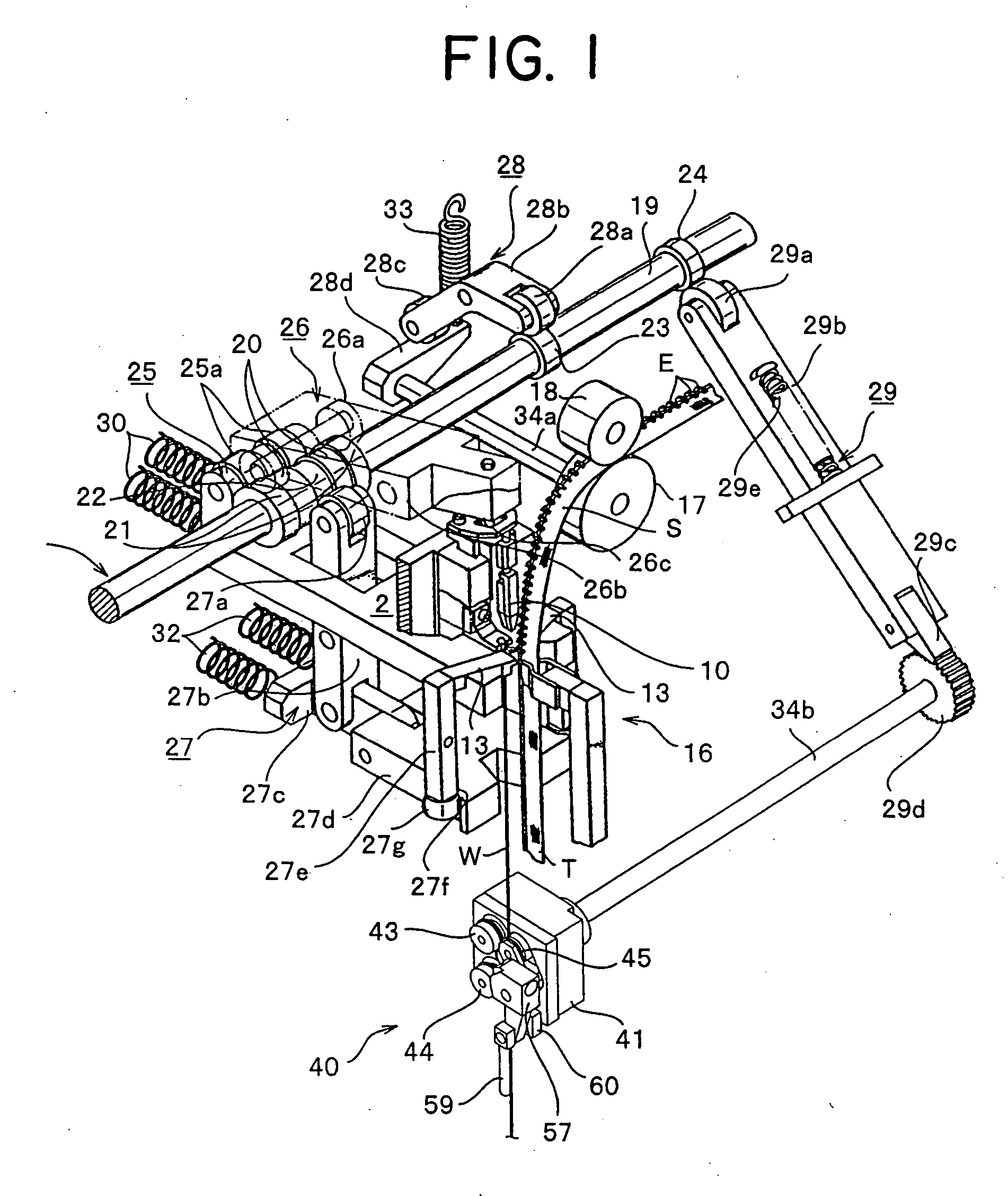
[0016] As a consequence, the pressing force of the ninth and tenth rollers against the seventh and eighth rollers is always equalized, and further, an elastic urging force weaker than that made by conventional a pair of rollers is obtained. Thus, even if the metallic linear material is fed in a slightly twisted state, of roller pairs to which the twisted portion is fed, the ninth and tenth rollers retract resisting the urging force and continue to feed the metallic linear material. Consequently, the twisted state is automatically corrected, thereby not damaging the metallic linear material. As a result, the metallic linear material is protected from being caught strongly by the seventh to tenth rollers, thereby protecting the ratchet wheel and ratchet pawl which are a drive source from a damage.
[0017] Preferably, the feeding unit comprises release and contact means for releasing and contacting the ninth and tenth rollers from and to the seventh and eighth rollers together with the roller support member. Consequently, exchange of the metallic linear material and inspection of the feeding roller are facilitated.
[0020] Further, the roller support member is constitute of a V-shaped lever member, the pair of the ninth and tenth roller is supported at both ends thereof while the central bent portion is supported such that the both ends are capable of rotating. In this case, when the central bent portion is urged toward the seventh and eighth rollers by the urging means perpendicularly to a straight line connecting the centers of the shafts of the seventh and eighth rollers, the pressing force of the ninth and tenth rollers against the seventh and eighth rollers is equalized easily, thereby achieving secure feeding of the metallic linear material.
[0023] In this case, if the pitch between teeth of each gear of the seventh to tenth rollers is set equal, the metallic linear material feeding speeds of all the rollers coincide with one another, thereby achieving smooth feeding of the metallic linear material. The effects which the present invention exerts are considerably great.

Problems solved by technology

Although an operating portion which operates simultaneously with a main operating portion can follow up an operation timing of the main operating portion at a conventional manufacturing speed, it has become incapable of following up accelerated speed, thereby often leading to reduction of productivity.
Thus, not only the metallic linear material but also the ratchet wheel and ratchet pawl which are a drive source of the drive roller are damaged, thereby leading to stop of manufacturing of the fastener stringer.

Method used


Image

  • Feeding unit for engaging element metallic linear material in continuous manufacturing apparatus for fastener stringer
  • Feeding unit for engaging element metallic linear material in continuous manufacturing apparatus for fastener stringer
  • Feeding unit for engaging element metallic linear material in continuous manufacturing apparatus for fastener stringer

Examples


Embodiment Construction

[0033] Hereinafter, a preferred embodiment of the present invention will be described specifically with reference to the accompanying drawings.

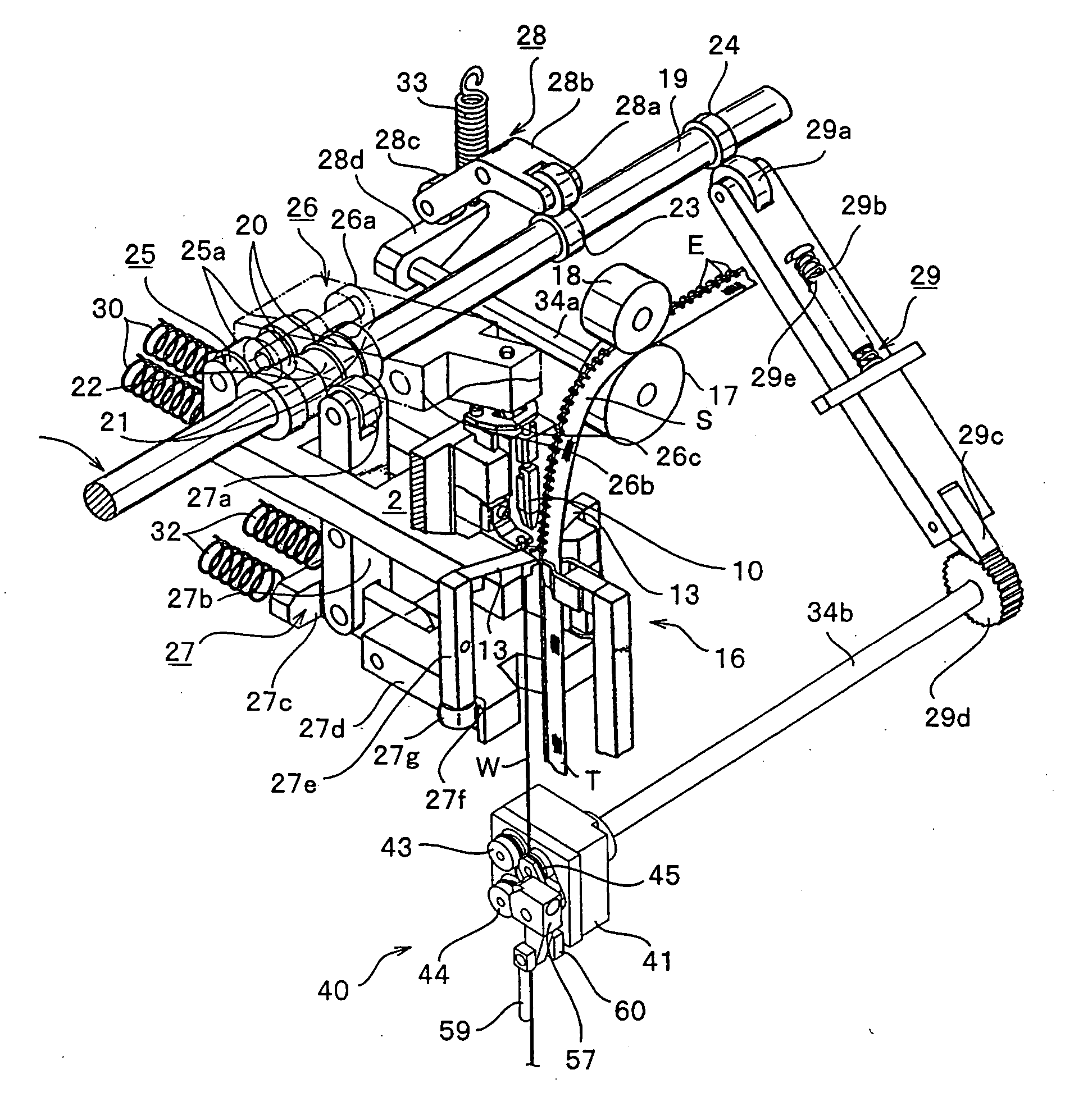
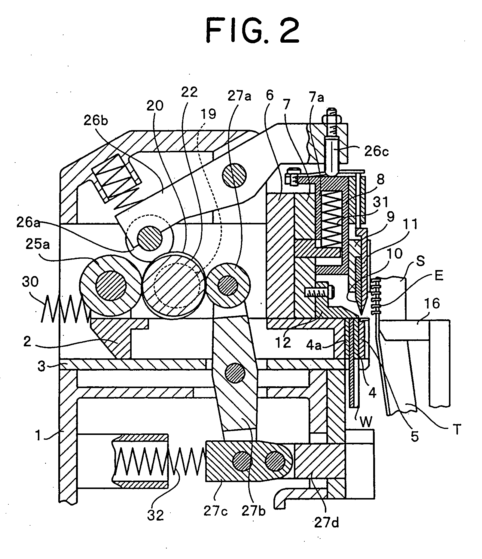
[0034]FIGS. 1 and 2 schematically show an example of a fastener stringer manufacturing apparatus of the present invention. The indicated structure is substantially not different from the apparatus disclosed in the Japanese Patent Publication No. 59-51813. Thus, the following outline of the apparatus is based on descriptions of the publication. In these figures, a first ram 2 is supported on a base 1 through a ram guide 3 so as to freely reciprocate horizontally, and a cutting die 4 and a forming die 5 for forming an engaging head of an engaging element E into a mountain-like shape are provided on the front portion of the first ram 2 in this order in the advancement direction of the first ram 2. The cutting die 4 has an introduction passage 4a for introducing an irregular shape linear material W for an engaging element, the irregular shape li...


PUM

PropertyMeasurementUnit
Metallic bondaaaaaaaaaa

Abstract

The invention provides a feeding unit for a metallic linear material having an irregular shaped section applicable to a continuous manufacturing apparatus for a fastener stringer, the feeding unit comprising the seventh and eighth rollers rotatably supported at their fixed positions, the ninth and tenth rollers opposing the seventh and eighth rollers and rotatably supported at both ends of a movable roller support member, wherein the roller support member is rotatably supported around its center and urged elastically in a direction perpendicular to a straight line connecting the centers of roller shafts of the seventh and eighth rollers, thereby the feeding roller protecting the metallic linear material from easily slipping out of feeding rollers, returning the linear material to its original track immediately even if the linear material slips out for a while, and feeding the metallic linear material stably and securely without damaging the linear material or ratchet wheel.

Description

BACKGROUND OF THE INVENTION [0001] 1. Field of the Invention [0002] The present invention relates to a feeding unit for metallic linear material applicable to a continuous manufacturing apparatus for fastener stringer which intermittently feeds an engaging element metallic linear material for a slide fastener to an engaging element implanting section, the metallic linear material having a substantially Y-shaped section molded preliminarily by rolling. [0003] 2. Description of the Related Art [0004] As for this kind of slide fastener engaging element, a long metallic linear material having a circular section is formed into a substantially Y shape in its lateral section through a plurality of mill rolls, and is intermittently fed by an amount corresponding to a single engaging element and successively cut out into a predetermined thickness by a cutting punch and a cutting die to obtain an engaging element material. By molding its engaging head into a mountain like shape by a forming p...

Claims


Application Information

Patent Timeline
IPC IPC(8): B32B37/00
CPCA44B19/46Y10T29/5117Y10T29/49785Y10T29/53304Y10T29/5101Y10T156/1712Y10T83/9411Y10T83/202B01D46/0041
Inventor IAI, KENICHIROMORIOKA, KOITSU
Owner YKK CORP
Learn More