
Active noise regulator

Inactive Publication Date: 2006-08-24
NAIR RAJENDRAN
View PDF7 Cites 4 Cited by
  • Summary
  • Abstract
  • Description
  • Claims
  • Application Information

AI Technical Summary

Benefits of technology

[0008] Prior art droop suppression circuits employ a reservoir capacitor charged to a higher potential than the load in order to provide an inrush of needed charge. The invention proposes a gated charge and gated discharge path for the reservoir capacitor. This allows for the depletion of most of the charge in the reservoir capacitor in response to a sudden load demand through the disconnection of the charging pathway and conduction through the discharge pathway. Discharge of the reservoir capacitor to ground potential or negative potentials is enabled by the energy developed in the discharge pathway inductances. During this process, the gated charge pathway remains disconnected. After the reservoir capacitor reaches the required (near zero or negative) potential, it is now capable of absorbing any voltage overshoot that results on the power grid of the load because of the load demand suddenly ceasing or reducing substantially. The inductive energy stored in the primary power pathway to the load from the voltage regulation modules, that would ordinarily cause a voltage overshoot, is instead recovered through a reconnection of the depleted ANR reservoir capacitor to the power grid when the load demand turns off or drops. The improved ANR therefore serves an energy recovery function while assisting in minimizing noise on the power grid at the load. Working symbiotically with the load device in maintaining load power integrity, one or more ANR's enable fast turn-on and turn-off of high-power loads.

Problems solved by technology

Greater levels of integration of transistors devices in ULSI chips, a consequence of device size scaling, leads to greater power consumption despite the reduction in operating voltages.
This leads to increasing operating currents, and consequently an increased need for stored charge in close proximity to devices in the nanoscale regime integrating 100's of millions of transistor devices.
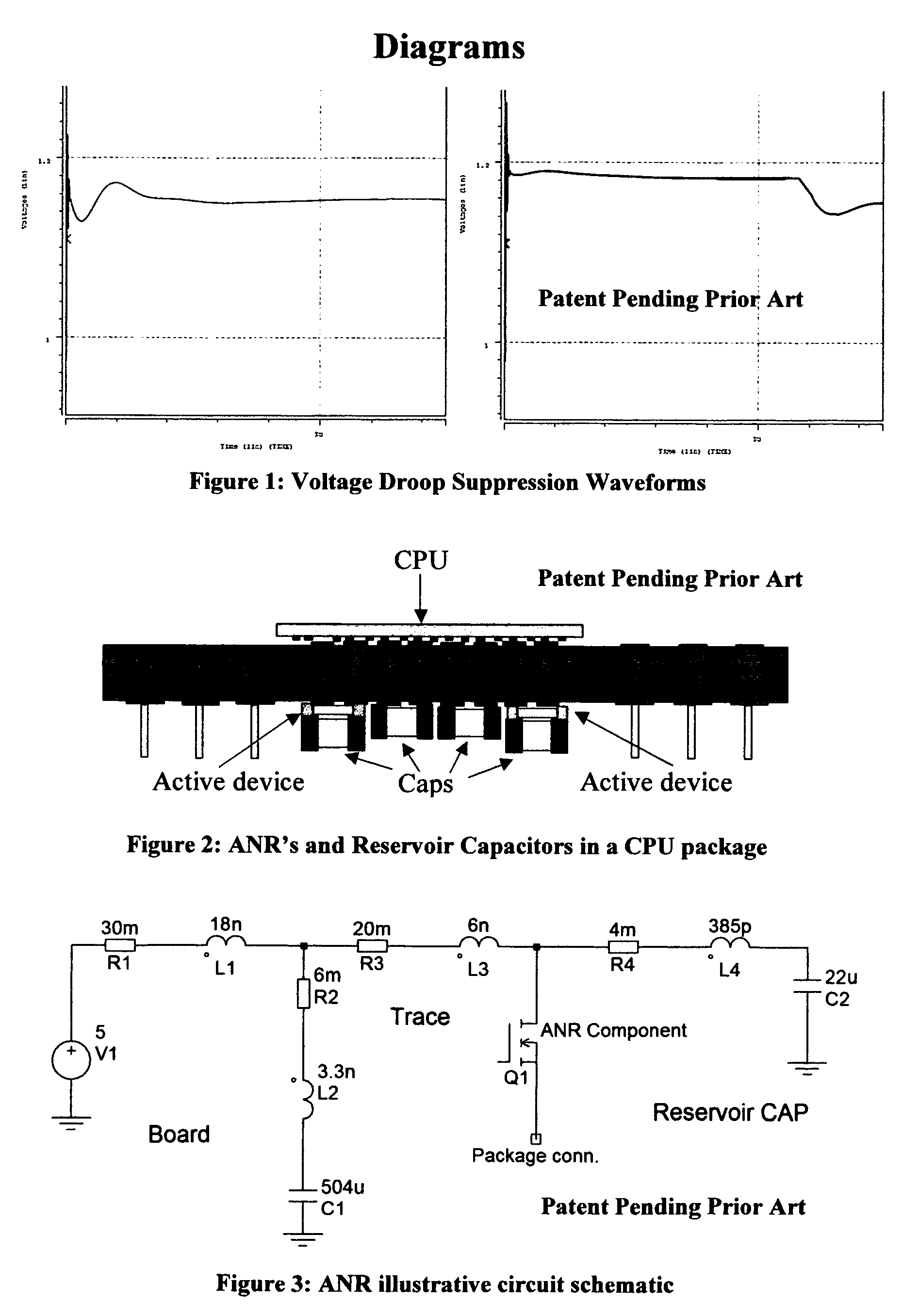
While these active devices assist in voltage droop suppression as shown in FIG. 1, they are subject to some limitations: These active devices, while minimizing voltage droop, may give rise to increased voltage overshoot upon sudden reduction of load current demand These active devices trade power for noise; they consume additional energy in the noise reduction function that impacts overall power system efficiency.
These disadvantages diminish the beneficial impact of such active circuits employed for noise reduction.

Method used


Image

  • Active noise regulator
  • Active noise regulator
  • Active noise regulator

Examples


Embodiment Construction

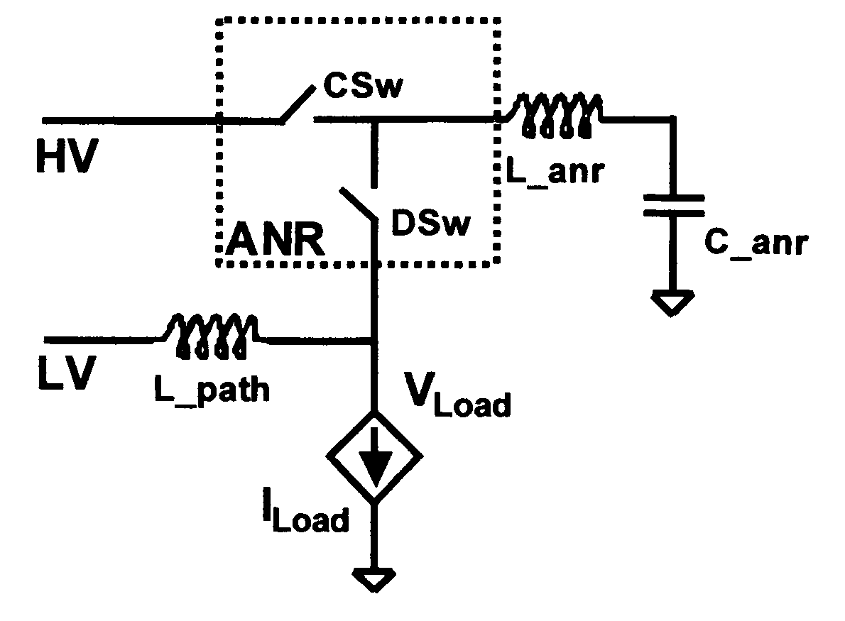
[0013]FIG. 4 illustrates an embodiment of the invention architecture. The two switches enclosed within the dashed-line box represent the active noise regulator (ANR) component. L_anr and C_anr represent the parasitic loop inductance and the capacitance of the reservoir capacitor attached to the ANR. CSw is the charging path switch and DSw is the discharge path switch device within the ANR. L_path is the path inductance from the voltage regulation modules that form the primary power supply to the load ULSI component which is represented by I_load. HV is the higher voltage provided to the ANR component and LV is the voltage provided by the voltage regulation module to the load ULSI component. V_load is the voltage at the power grid of the ULSI component.

[0014]FIG. 1 shows simulation viewgraphs for a prior art voltage droop suppression component. The graph on the left of the figure corresponds to a plot of voltage with time on a power grid disturbed by a high-current, sudden load dema...


PUM


Abstract

The invention proposes noise suppression circuits mounted on the package of a high power, high frequency ULSI component. In this architecture, termed an active noise regulator (ANR), charge is stored on dedicated reservoir capacitors at a voltage substantially higher than the operating voltage of the ULSI device. These reservoir capacitors are mounted upon active circuits packaged to match the size and form factor of the capacitors and this assembly is then attached to the package substrate. Charge is conveyed from the reservoir capacitors to the ULSI power grid when there is a sudden load current demand in the ULSI device. The capacitors are depleted by the flow of charge through inductances in the discharge pathway. The capacitors are then recharged either by the overshoot that results from a sudden release of the ULSI load current demand or by a gated charging pathway connected to a high voltage supply. The use of the depleted reservoir capacitor to absorb power grid voltage overshoots assists in maintaining power integrity for the ULSI device while conserving energy in the power pathways. The circuits within the active device may be any combination of semiconductor switches and / or voltage regulators, and may also contain voltage and current sensing circuitry.

Description

CROSS-REFERENCE TO RELATED DOCUMENTATION [0001] This application relates to U.S. Utility patent application Ser. No. 10 / 875,022 dated the 24th of Jun. 2004, entitled “Voltage Droop Suppressing Active Interposer” and to U.S. Utility patent application Ser. No. 10 / 766,270 dated the 29th of Jan. 2004, entitled “Method & apparatus for transient suppressing high-bandwidth voltage regulation”.TECHNICAL FIELD OF THE INVENTION [0002] Embodiments of the invention relate to electronic circuitry commonly employed to provide regulated voltages to other electronic, electro-mechanical or electro-optic devices and systems. Such circuitry falls under the broad category of power delivery management electronics. BACKGROUND & PRIOR ART [0003] Greater levels of integration of transistors devices in ULSI chips, a consequence of device size scaling, leads to greater power consumption despite the reduction in operating voltages. This leads to increasing operating currents, and consequently an increased ne...

Claims


Application Information

Patent Timeline
IPC IPC(8): H03K3/356
CPCH03K17/16
Inventor NAIR, RAJENDRAN
Owner NAIR RAJENDRAN
Learn More