
Continuous casting mold and a continuous casting method of copper alloy

a technology of copper alloy and continuous casting method, which is applied in the field of continuous casting mold and continuous casting method of cu alloy, can solve problems such as fatigue strength, and achieve the effects of ensuring the quality of the final produ

Inactive Publication Date: 2006-08-17
SUMITOMO METAL IND LTD
View PDF4 Cites 32 Cited by
  • Summary
  • Abstract
  • Description
  • Claims
  • Application Information

AI Technical Summary

Benefits of technology

[0028] According to the present invention, a continuous casting mold capable of continuously and stably producing a sound slab can be provided. A continuous casting method of a Cu alloy capable of ensuring excellent characteristics such as strength, electric conductivity, bending workability and fatigue strength of the final product after working and heat treatment, can be provided. Particularly, in application to casting of a Cu alloy containing Zr, Ti, Cr, Ta, V and so on, which are elements that easily form into carbides, a profound effect can be obtained. The present invention is highly effective not only for Cu alloys but also for such materials as non-ferrous metals other than Cu alloys.

Problems solved by technology

On the other hand, the improvement in workability such as bending workability due to the downsizing of parts, the improvement in heat resistance in order to ensure usability even in relatively severe environments, and the improvement in fatigue strength are also important problems.
This method essentially requires a hot process such as a solution treatment or a hot working in the later production process because of a low cooling rate in the cooling process after solidification.

Method used


Image

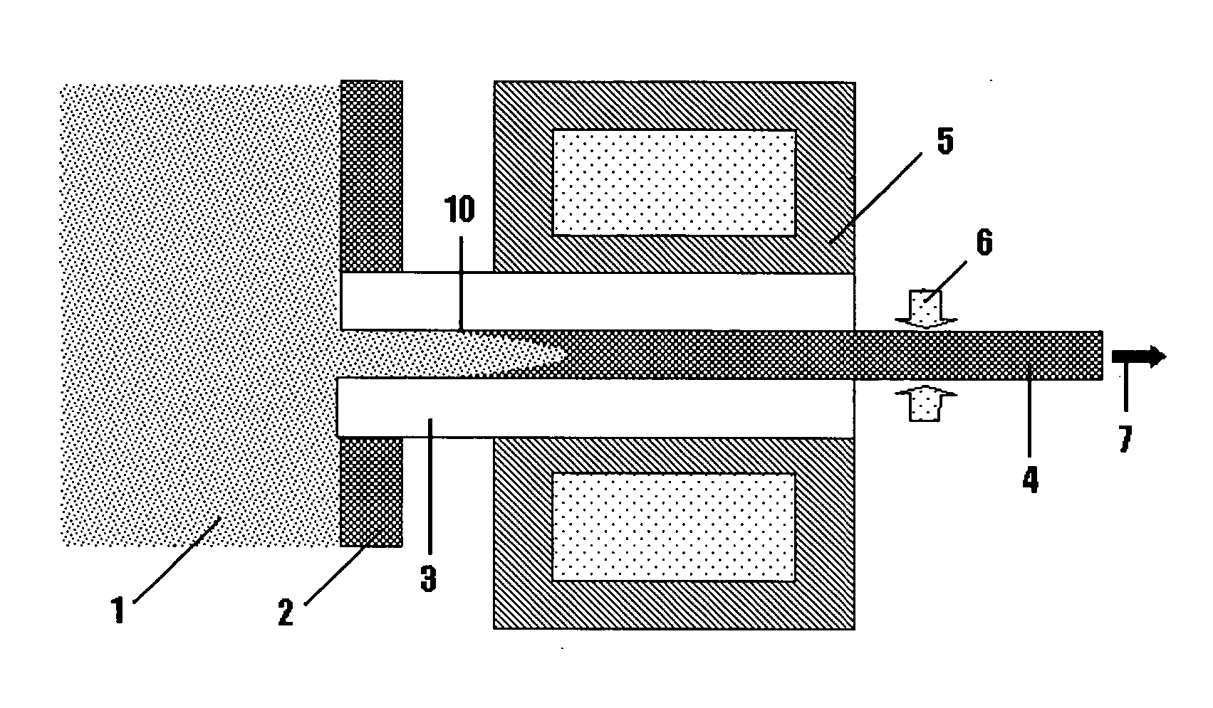
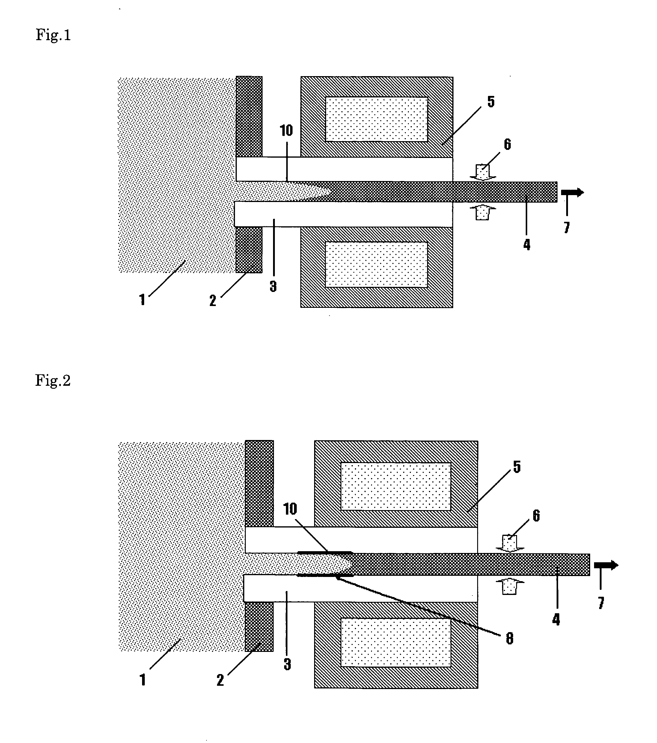
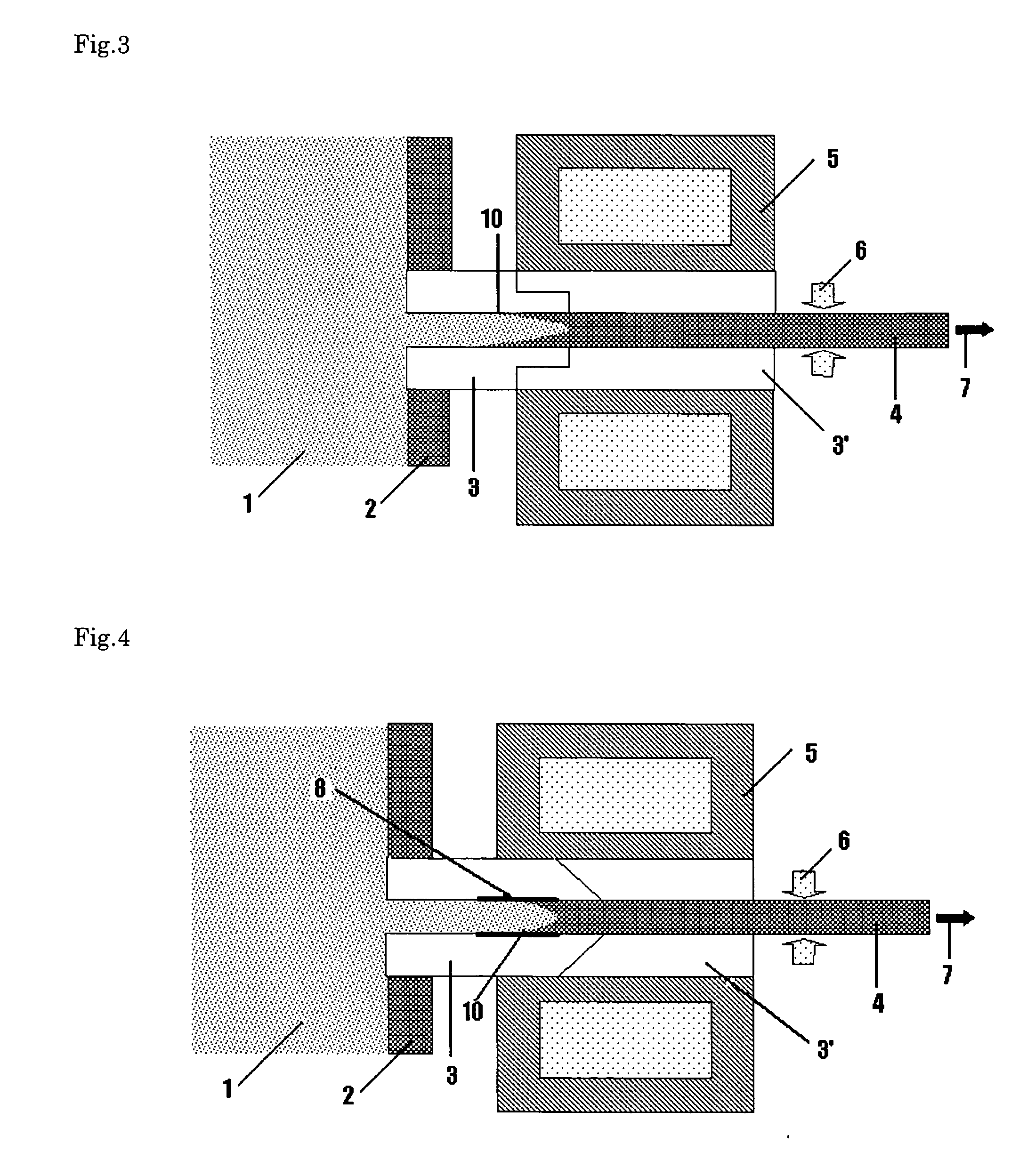
  • Continuous casting mold and a continuous casting method of copper alloy
  • Continuous casting mold and a continuous casting method of copper alloy
  • Continuous casting mold and a continuous casting method of copper alloy

Examples


example a

[0096] Cu alloys containing 2.0±0.1 wt % of Ti, 1.0±0.1 wt % of Cr, 0.4±0.02 wt % of Sn, and 0.1±0.01 wt % of Zn were melted in a high frequency vacuum melting furnace, and a continuous casting test was carried out in 30 kinds of various production methods shown in Tables 1 and 2. Each Cu alloy melt was transferred to a holding furnace, and a slab of 20 mm×200 mm section was intermittently pulled out in a predetermined condition while holding the temperature of the furnace at 1250° C. As a refractory of the melting furnace and the holding furnace, graphite was used. The oxidation of the melt was suppressed by an Ar gas flow during pouring in addition to charcoal covering. In each test, a water-cooled jacket composed of the Cu alloy was located adjacent to the mold in order to perform primary cooling, and the slab leaving the mold was cooled again by an air-water mixed spray. The temperature measurement was performed basically after leaving the mold by use of a thermocouple or radiat...

example b

[0101] There are 34 kinds of Cu alloys of the chemical compositions shown in Table 3, which were smelted similarly to Example A. A continuous casting test was carried out while varying the production condition, and they were evaluated in the same method as Example A. The results are shown in Tables 4 and 5. A satisfactory result was obtained in any mold, any casting condition and any chemical composition in the present invention. In contrast, an unsatisfactory result for quality was obtained using comparative molds.

TABLE 3AlloyNo.TiCrZrAgSnMnCoSiMgFeAlZnNiPOthers1—0.392.95————————————22.010.40—0.25——————————Mg: 0.1, Ca: 0.131.02 .200.99————————————42.991.01—————————————5—0.993.99————————————6—2.000.12———————————Li: 0.1, Sc: 0.570.981.97—5.00———————————83.01—2.01————————————91.014.00—0.10———————————105.000.99———————————0.001Nb: 0.2, Ge: 2.0113.010.97——0.41——0.49——0.51——Hf: 1.0, Bi: 0.512—0.981.99—0.10——0.201.00——0.21———131.980.99——0.35——0.04——0.29—1.500.001Sb: 1.1140.500.990.05————...

example c

[0104] For the three kinds of alloys shown in Table 6, slabs of 20 mm×200 mm section were casted by use of a mold composed of graphite with bulk density of 1.82, with a glassy carbon applied to the inner wall, and the influence of the cooling rate on characteristics was examined by varying the water quantities of primary cooling and secondary cooling, and varying the cooling rate from the solidification start point to 600° C. The cooled slabs were cold rolled to 3 mm, then aged at 400° C. for 2 hr under an inert gas atmosphere followed by cold rolling to 0.5 mm, and finally aged at 350° C. for 6 hr. The electric conductivity and tensile strength by tensile test of the resulting test materials were evaluated by the following methods.

[0105] [Table 6]

TABLE 6AlloyCoolingNo.TiCrZrrate(° C. / s)TS(MPa)IACS(%)Evaluation*RemarksComparative352.001.51—0.10——XNot evaluated because of cracking during cold rollingThe present352.011.51—0.5080240◯invention351.981.49—5.0095627◯351.991.51—10.00117419...


PUM

PropertyMeasurementUnit
Temperatureaaaaaaaaaa
Fractionaaaaaaaaaa
Fractionaaaaaaaaaa

Abstract

A continuous casting mold for a Cu alloy, using any one member selected from a glassy carbon, a metal-based self-lubricating composite or a graphite with a bulk density exceeding 1.92, at least for the mold member including the solidification starting position of the Cu alloy melt. A continuous casting mold for a Cu alloy, composed of any one member selected from a graphite, a ceramic and a metal member or of a combination of two or more parts of members thereof, in which at least the inner wall in the solidification starting position of the Cu alloy melt is coated with a self-lubricant or a metal-based self-lubricating composite material. A continuous casting method of a Cu alloy, comprised of giving, at the time of continuously casting the Cu alloy by an intermittent pulling out method, a vibration that has a frequency larger than the slab intermittent pulling out frequency by two orders or more and that has a component vertical to the pulling out direction of the slab, or continuously supplying a lubricant or an anti-sticking material between the inner wall of the mold and the slab.

Description

TECHNICAL FIELD [0001] The present invention relates to a continuous casting mold and a continuous casting method of a Cu alloy, particularly, a casting mold used for a direct-connection type of continuous casting machine, in which a mold is directly connected to a holding furnace, and a continuous casting method of a Cu alloy using this mold. BACKGROUND ART [0002] Along with the recent development of Information Technology, particularly, in the technology of the cellular phone, portable computer or the automobile electronic equipment, it has become more important to enhance the performance of a Cu alloy used for electric and electronic parts such as a lead frame, a terminal, a connector, a spring or a contact element. The typical first necessary characteristic is higher strength for a reduction in weight, and the second is higher electric conductivity for suppressing a rise of electric resistance caused by reduction in the sectional area due to the reduction in weight. On the other...

Claims


Application Information

Patent Timeline
IPC IPC(8): B22D11/00B22D11/059B22D11/12B22D11/14
CPCB22D11/004B22D11/059B22D11/12C22C9/10C22C9/00C22C9/02C22C9/04B22D11/143
Inventor MAEHARA, YASUHIROYONEMURA, MITSUHARUNAKAJIMA, KEIJIYOSHIDA, NAOTSUGUAOKI, MASAHIRO
Owner SUMITOMO METAL IND LTD
Learn More