Feed forward amplifier employing positive feedback pilot generation with automatic level control

a technology of automatic level control and pilot generation, which is applied in the direction of amplifiers, amplifiers with semiconductor devices/discharge tubes, amplifiers, etc., can solve the problems of increasing the difficulty of pilot power generation, increasing the cost, and consuming part of the rated power handling capability of main amplifiers, so as to reduce the level of the generated pilot signal

Inactive Publication Date: 2006-08-10
INTEL CORP
View PDF3 Cites 10 Cited by
  • Summary
  • Abstract
  • Description
  • Claims
  • Application Information

AI Technical Summary

Benefits of technology

[0016] In a preferred embodiment of the pilot detection and generation system, the automatic level control circuit further comprises one or more outputs providing a variable signal representative of the signal power of the output of the detector circuit. The automatic level control circuit preferably also comprises a power detector and a feedback circuit for stabilizing the maximum level of the output of the detector circuit and providing it as the level stabilized signal, and a variable voltage attenuator configured in the feedback circuit for reducing the level of the signal from the detector circuit. The pilot detection and generation system preferably further comprises a local oscillator and the detector circuit comprises a first multiplier coupled to the local oscillator and mixing the local oscillator signal with the amplifier RF output and a bandpass filter coupled to the output of the first multiplier and providing as an output the signal component representative of a band limited portion of the amplifier RF output. The pilot generator circuit preferably further comprises a second multiplier coupled to the local oscillator for mixing the local oscillator signal with the level stabilized signal and providing as an output the pilot signal.

Problems solved by technology

This requirement is critical for modern wireless communication systems but it is increasingly difficult to achieve.
This is due primarily to the bandwidth requirements of modern wireless communication systems which are placing increasing demands on amplifier linearity.
Prior art pilot generation and detection systems must contend with various problems.
Third, the pilot power consumes part of the rated power handling capability of the main and error amplifiers.
As a result, larger transistors are required to meet customer specifications, which in turn increases the cost.
In general, the quadrature requirement adds expense and complexity to the pilot generation or detection circuitry, and adds complexity to the post-detector digital processing.
For prior art approaches, the amount of pilot power injected into the main amplifier path is therefore limited to prevent excessive residual spurs.
This makes the detection circuitry more susceptible to noise, making the alignment process for the second loop less robust.
In the prior art, the pilot power consumes part of the power rating of the main and error amplifiers.
That is, the presence of the pilot power affects the amount of distortion produced rather than damaging the transistor.
The problem with turning off the pilot is that subsequent misalignments in the second loop cannot be detected.
This would make the amplifier very susceptible to thermally induced drift in the second loop gain or phase.

Method used


Image

  • Feed forward amplifier employing positive feedback pilot generation with automatic level control
  • Feed forward amplifier employing positive feedback pilot generation with automatic level control
  • Feed forward amplifier employing positive feedback pilot generation with automatic level control

Examples


Embodiment Construction

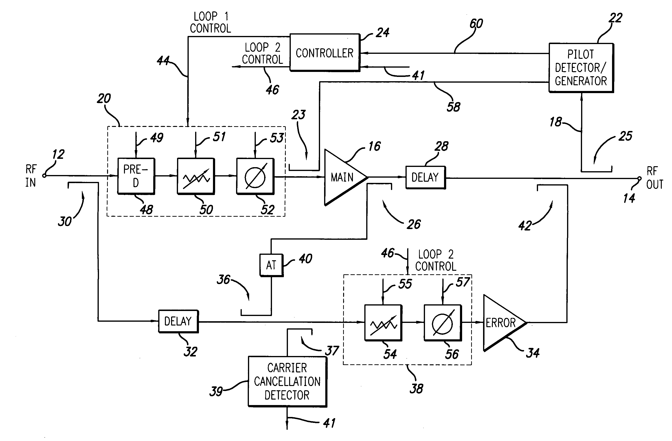
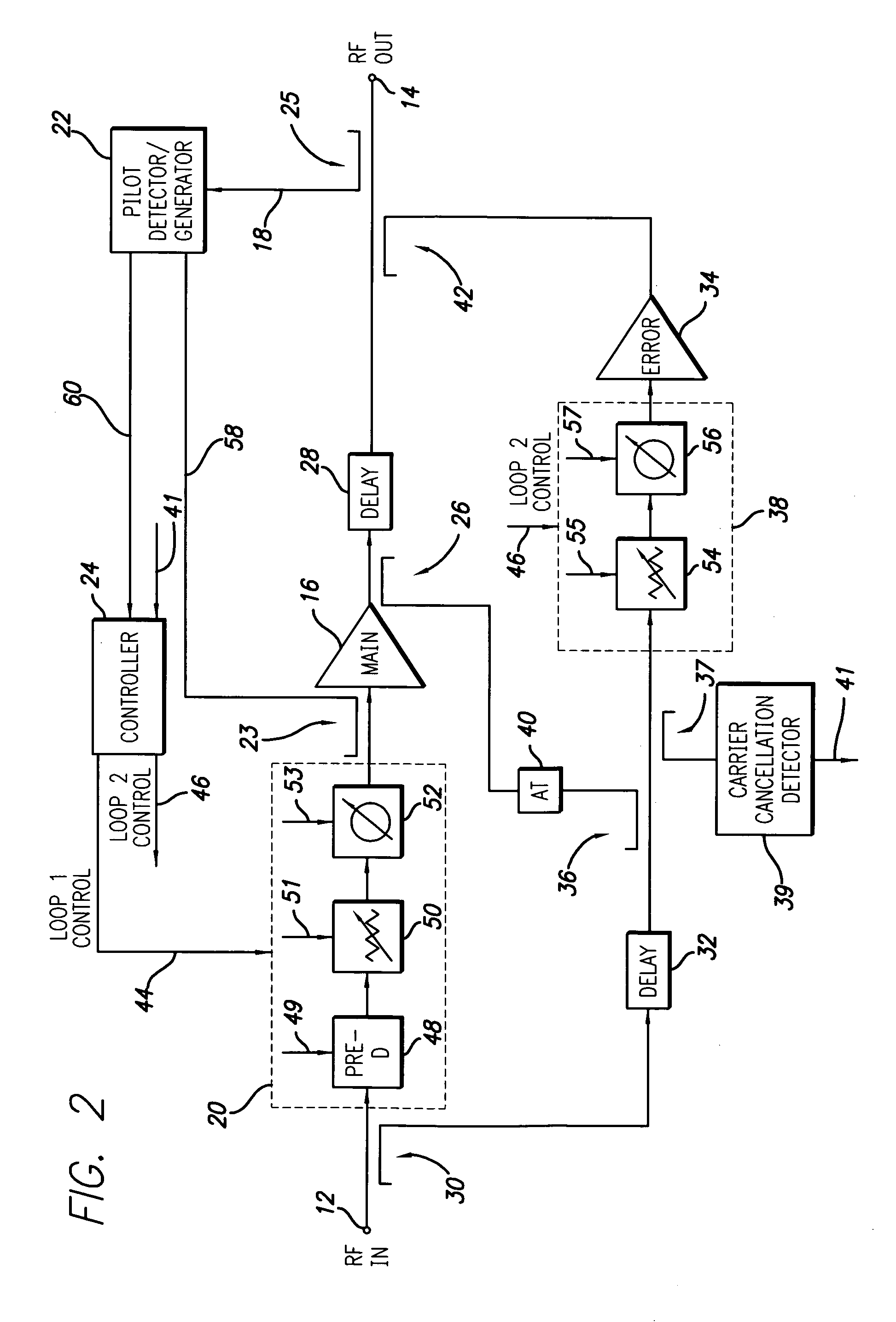
[0028] A feed forward amplifier in accordance with a preferred embodiment of the present invention is shown in FIG. 2 in a block schematic drawing. The feed forward amplifier employs a positive feedback pilot generation system, a preferred embodiment of which is shown in FIG. 3. The feed forward amplifier of the present invention may incorporate known features other than the novel aspects described in detail herein and such known features will not be described in detail. For example, additional features of a feed forward amplifier architecture and control system are described in U.S. patent application Ser. No. 10 / 365,111 filed Feb. 12, 2003, the disclosure of which is incorporated herein by reference in its entirety.

[0029] Referring to FIG. 2, the feed forward amplifier includes an input 12 which receives an input RF signal to be amplified and an output 14 which outputs the amplified RF signal. The RF signal may be a high bandwidth signal such as a CDMA (Code Division Multiple Acc...


PUM


Abstract

A feed forward amplifier and method of amplification are disclosed. The amplifier output is used to generate a pilot signal via feedback using uncancelled noise in the amplifier output. An automatic level control circuit maintains the pilot signal at a substantially constant level when the detected uncancelled noise in the amplifier output is above a threshold level. The generated pilot signal strength is allowed to vary when the detected uncancelled noise in the amplifier output is below the threshold and disappears automatically when the amplifier is aligned.

Description

RELATED APPLICATION INFORMATION [0001] The present application is a continuation-in-part of Ser. No. 10 / 838,985 filed May 5, 2004 which claims priority under 35 U.S.C. 119(e) to provisional application Ser. No. 60 / 468,444 filed May 7, 2003 and the present application also claims priority under 35 U.S.C. 119(e) to provisional application Ser. No. 60 / 659,744 filed Mar. 8, 2005, the disclosures of which are incorporated herein by reference in their entirety.BACKGROUND OF THE INVENTION [0002] 1. Field of the Invention [0003] The present invention relates to RF power amplifiers and amplification methods. More particularly, the present invention relates to feed forward power amplifiers and methods of using a pilot to align the loops of a feed forward amplifier. [0004] 2. Description of the Prior Art and Related Information [0005] A primary goal of RF power amplifier design is linearity over the range of power operation. Linearity is simply the ability to amplify without distortion. This r...

Claims


Application Information

Patent Timeline
Patent Type & Authority Applications(United States)
IPC IPC(8): H03F3/66
CPCH03F1/26H03F1/3235
Inventor BRAITHWAITE, RICHARD NEILHUNTON, MATTHEW J.
Owner INTEL CORP
Why Eureka
Try Eureka