
Complex-shape compressed gas reservoirs

a compressed gas and complex technology, applied in the field of cooling, can solve the problems of cumbersome approach, high cost, and potential failure, and achieve the effect of effective cooling system and maximum cooling efficiency

Inactive Publication Date: 2006-08-10
INVENTION FACTORY
View PDF26 Cites 50 Cited by
  • Summary
  • Abstract
  • Description
  • Claims
  • Application Information

AI Technical Summary

Benefits of technology

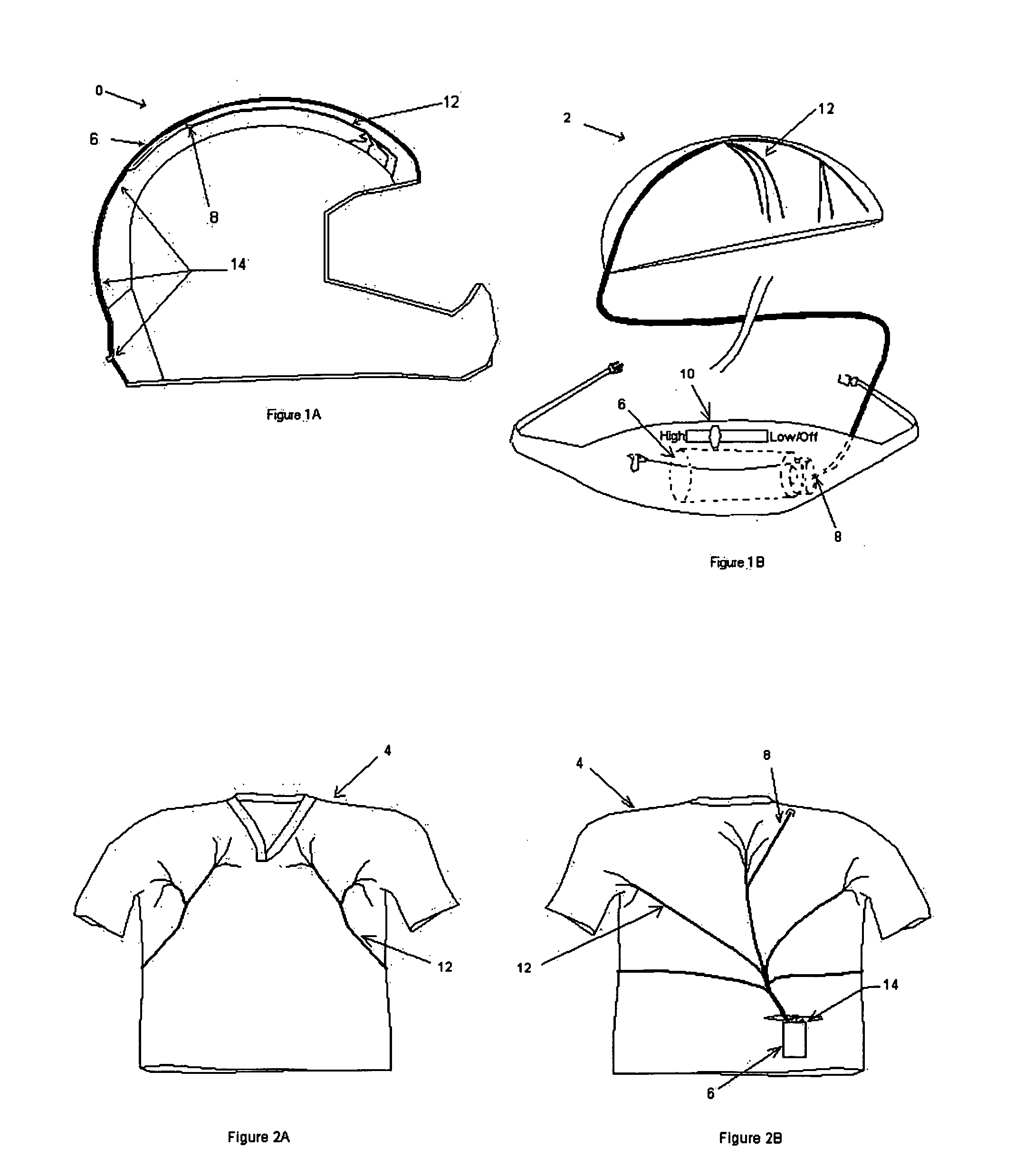
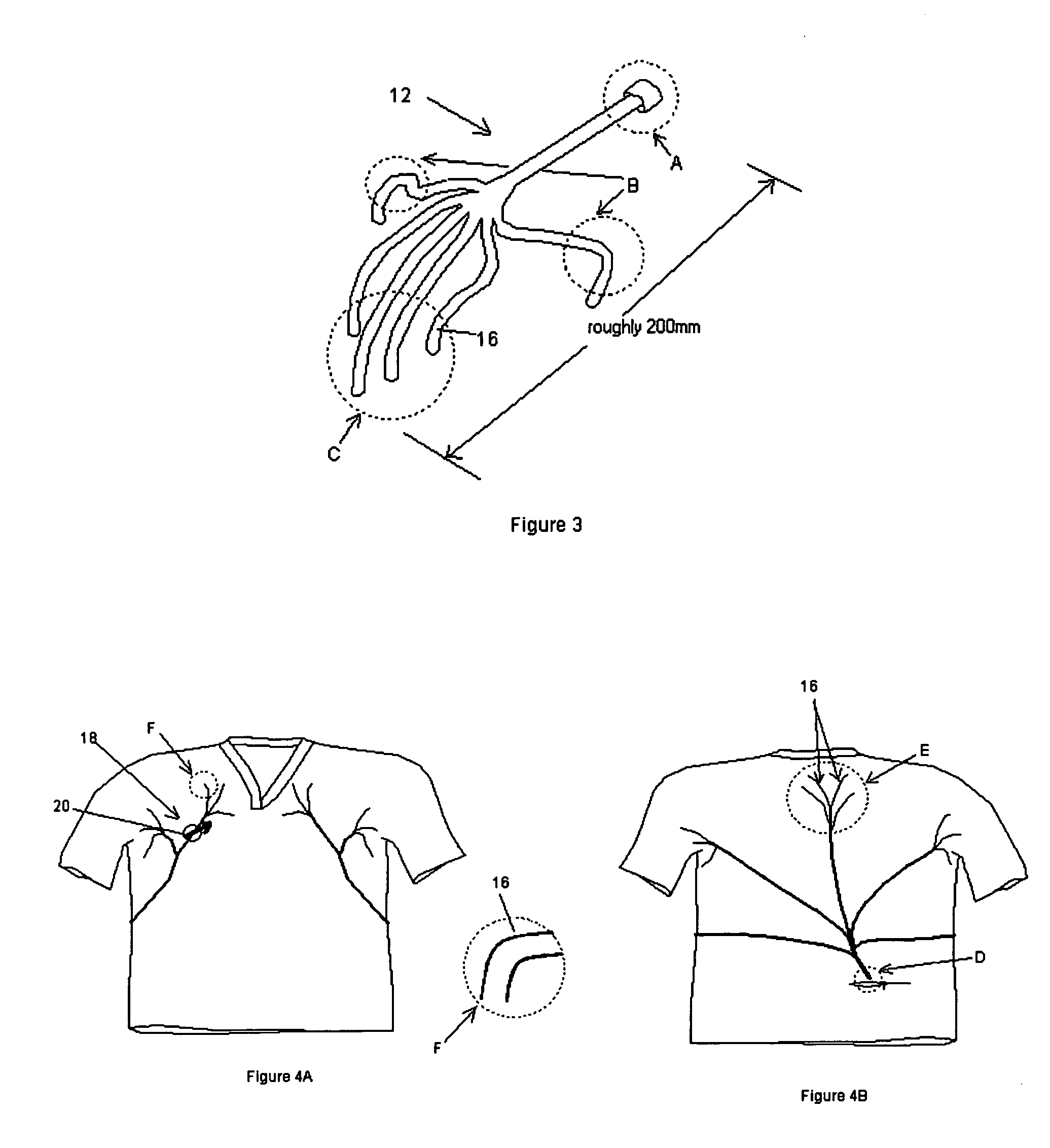
[0016] Using co-molding baffle members of various shape and orientation, desirable composite reservoir structures can be formed. The baffles sections will offer support and structure to the system. Also, they provide an elegant approach to interconnecting the constituent chambers of the reservoir. Without such interconnection, ingress and egress of fluid therefrom or therebetween would require individual external plumbing to each section. Such an approach would be not only cumbersome, but also costly and possibly prone to failure. Accordingly, the baffle-type multi-chamber construction provides not only simplicity, but also a certain robustness to the system. Especially considering that the reservoirs are ideally intended for high-pressure applications, the latter factor may be particularly pertinent.
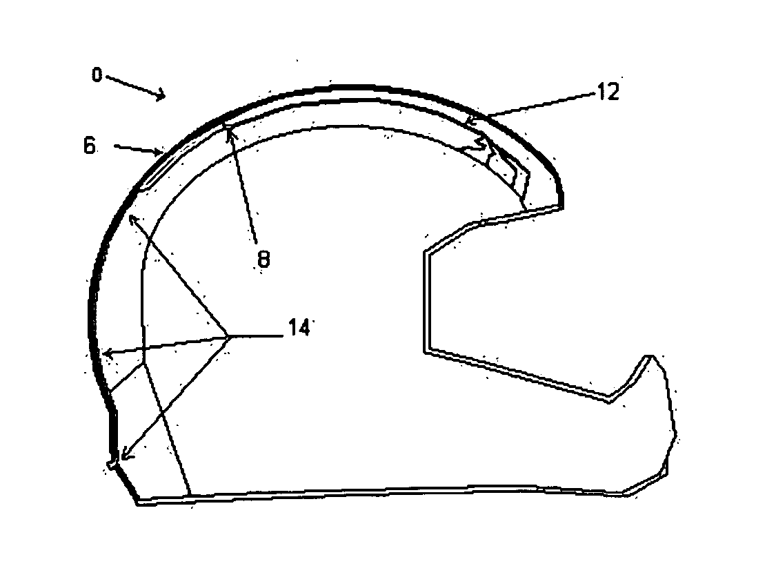
[0023] To minimize weight and system bulk or complexity, the reservoir canister itself could feature a dial switch with “Off-Low-High” settings (the Control System) as well as a valve stem much like that of a bicycle tube (the Fill System). The user would fill the reservoir from a source of high-pressure gas, set the control system to “Low” and experience cooling in the vest through a continuous stream or short bursts of compressed gas being emitted at various points close to the skin. Increasing the control mechanism to the “High” setting will increase the duration and / or frequency of the bursts or the flow rate of the continuous delivery of compressed gas to the wearer's body. Of course, other system and control configurations are possible as well, including those elaborated upon below.
[0024] By delivering gas in a compressed state from a high pressure reservoir, the gas is still expanding as it contacts the body of the wearer. Thus the compressed gas cooling system utilizes Charles' Law of evaporative cooling which states that the temperature of any gas must drop as the pressure drops; this cooled gas provides for conductive heat transfer (cooling). Secondly, since the relative humidity of the gas originating from the high pressure reservoir is very low, it should provide for a high degree of evaporative cooling as the gas absorbs moisture from the body of the wearer and escapes the garment or such other apparatus the system may incorporate. This effect will be most pronounced in humid environments.
[0025] The compressed gas cooling system employed in connection with the subject pressure vessel advantageously allows for a minimum of impediments to the escaping gas, providing the user with the feeling of air moving by the cooling sites. That is to say, in the case of a jersey the construction is mesh or another fabric that is able to breathe, thereby allowing the decompressed / expanded air to escape from adjacent the user's body.

Problems solved by technology

Such an approach would be not only cumbersome, but also costly and possibly prone to failure.

Method used


Image

  • Complex-shape compressed gas reservoirs
  • Complex-shape compressed gas reservoirs
  • Complex-shape compressed gas reservoirs

Examples


Embodiment Construction

[0043] Before the present invention is described in detail, it is to be understood that this invention is not limited to particular variations set forth and may, of course, vary. Various changes may be made to the invention described and equivalents may be substituted without departing from the true spirit and scope of the invention. In addition, many modifications may be made to adapt a particular situation, material, composition of matter, process, process act(s) or step(s), to the objective(s), spirit or scope of the present invention. All such modifications are intended to be within the scope of the claims made herein.

[0044] Methods recited herein may be carried out in any order of the recited events which is logically possible, as well as the recited order of events. Furthermore, where a range of values is provided, it is understood that every intervening value, between the upper and lower limit of that range and any other stated or intervening value in the stated range is enc...


PUM

PropertyMeasurementUnit
Pressureaaaaaaaaaa
Internal pressureaaaaaaaaaa
Thicknessaaaaaaaaaa

Abstract

Portable cooling systems, employing a high pressure reservoir adapted to ergonomically interface with a user and / or a wearable article to deliver a flow of cooling gas through a conduit system are provided. Such a system is adapted to provide powered cooling to locations where only very small and portable cooling systems can fit. Various user retainable appliances or articles may have cooling features incorporated therein. The molded plastic high pressure reservoir may have other uses as well.

Description

RELATED APPLICATIONS [0001] This filing is a continuation-in-part of U.S. patent application Ser. No. 10 / 910,010 filed Aug. 2, 2004 and claiming the benefit of Provisional Patent Application Ser. No. 60 / 506,850 filed Sep. 30, 2003, each of which application is incorporated by reference herein in its entirety as if specifically set forth below.FIELD OF THE INVENTION [0002] This invention relates to the cooling of people or such things as race or stock animals, etc. More particularly, certain aspects of the invention are directed to user-retained or portable cooling systems, especially the supply of compressed gas for such cooling. BACKGROUND OF THE INVENTION [0003] Devices to actively effect cooling fall into several basic categories. Heat pump type air-conditioning devices provide a closed loop system that compress and expand gas without releasing it in order to provide a low-temperature interface. These systems are heavy, but can be built to offer tremendous cooling loads. [0004] E...

Claims


Application Information

Patent Timeline
IPC IPC(8): F17C1/00
CPCA41D13/0053A42B3/285A42C5/04F17C1/00F17C2201/0104F17C2201/0157F17C2201/0166F17C2201/0171F17C2201/0176F17C2201/058F17C2203/0617F17C2203/0648F17C2203/066F17C2203/0663F17C2203/0673F17C2205/0146F17C2205/0157F17C2205/0323F17C2205/0338F17C2209/2118F17C2221/014F17C2223/0123F17C2223/035F17C2223/036F17C2250/032F17C2250/034F17C2250/0439F17C2260/011F17C2260/018F17C2270/07
Inventor DEFOSSET, JOSH P.
Owner INVENTION FACTORY
Learn More