
Filter medium

a filter cloth and filter medium technology, applied in the field of filter cloth, can solve the problems of physical deterioration, physical deterioration, and physical deterioration of filter cloth while it is used, and achieve the effects of small rise in pressure loss, excellent dust collection efficiency, and high mechanical strength

Active Publication Date: 2006-08-03
TORAY IND INC
View PDF8 Cites 25 Cited by
  • Summary
  • Abstract
  • Description
  • Claims
  • Application Information

AI Technical Summary

Benefits of technology

[0012] In view of the above-mentioned technical background, the present invention provides a filter fabric excellent in dust-collecting efficiency, small in the rise of pressure loss after pulse cleaning and high in mechanical strength.
[0013] Furthermore, the present invention provides a dense filter fabric excellent in dust-collecting efficiency, excellent in thermal dimensional stability at high temperature and uniform in the fabric uniformity.
[0018] The first invention provides a filter fabric containing polyphenylene sulfide fibers, comprising at least two webs, one of which on the dust side contains 50 wt % or more of heat resistant fibers with a fiber diameter of 15 μm or less, while the other web on the clean side contains 50 wt % or more of heat resistant fibers with a fiber diameter of 20 μm or more. Therefore, the filter fabric is excellent in dust-collecting efficiency, small in the rise of pressure loss after pulse cleaning and excellent in mechanical strength.
[0019] Furthermore, the second invention provides a filter fabric containing polyphenylene sulfide fibers, comprising a web containing polyphenylene sulfide staple fibers with their fineness kept in a range from 1 to 3 dtex and fluorine-based staple fibers with their fineness kept in a range from 2 to 4 dtex. Therefore, the filter fabric is excellent in dust-collecting efficiency, excellent in thermal dimensional stability at high temperature, uniform in the fabric uniformity, and having few defects such as pinholes.

Problems solved by technology

Meanwhile, environmental regulations tend to be more severe in the world, and especially the PM2.5 regulations that are going to be enacted in USA may be applied also in Japan.
Moreover, when such filter fabrics are used, for example, in refuse incinerators, the chemical deterioration caused by high temperature exhaust gases and the chemicals, etc. contained in the exhaust gases takes place, and at the same time, in addition, the physical deterioration such as the wearing due to the contact with the cage and the flexing fatigue respectively caused by the pressure loss during exhaust gas filtration and by the pulse jetting during back-pulse cleaning also takes place.
This method is certainly good in dust release characteristics and dust collection performance, but since it is insufficient in the stiffness at high temperature and abrasion resistance, it has such a problem that the filter cloth is physically progressively deteriorated and broken while it is used.
However, since fluorine fibers are relatively low in stiffness, there is a fear that the stiffness especially at high temperature declines.
Furthermore, since fluorine fibers are insufficient in abrasion resistance, there is such a problem that the filter cloth is broken due to physical deterioration during use.
This method can certainly enhance the dust-collecting efficiency owing to the very fine fibers of the felt surface layer, but has a problem that increased processing steps raise the processing cost.
This method is intended to enhance the mechanical strength by laminating a woven fabric composed of glass fibers, but has such problems that since the glass fibers are low in the resistance against alkaline chemicals, a heat resistant filter cloth using the chemical resistance of PPS fibers cannot be provided and that the strength decline during wet heat treatment (autoclave treatment) is very large.
However, this invention uses PPS fibers with a 180° C. dry heat shrinkage rate of 3% or more, and does not improve the dimensional stability of a nonwoven fabric filter using PPS fibers.
Furthermore, the filter cloth has a problem that when PPS fibers and other fibers are blended, blending irregularity is likely to occur.
However, the filter cloth has such problems that since the air permeability in the initial state is so low as to increase the initial pressure loss, the life of the filter cloth is shortened, and that the capability of treating the exhaust gas greatly declines.
Moreover, it has a problem that plural processing steps of laminating a web composed of staple fibers of polytetrafluoroethylene and entanglement treatment are necessary after preparation of a heat resistant felt substrate.
Furthermore, it has a problem that the laminated web layer composed of staple fibers of polytetrafluoroethylene is separated by impact during use as a bag filter.

Method used

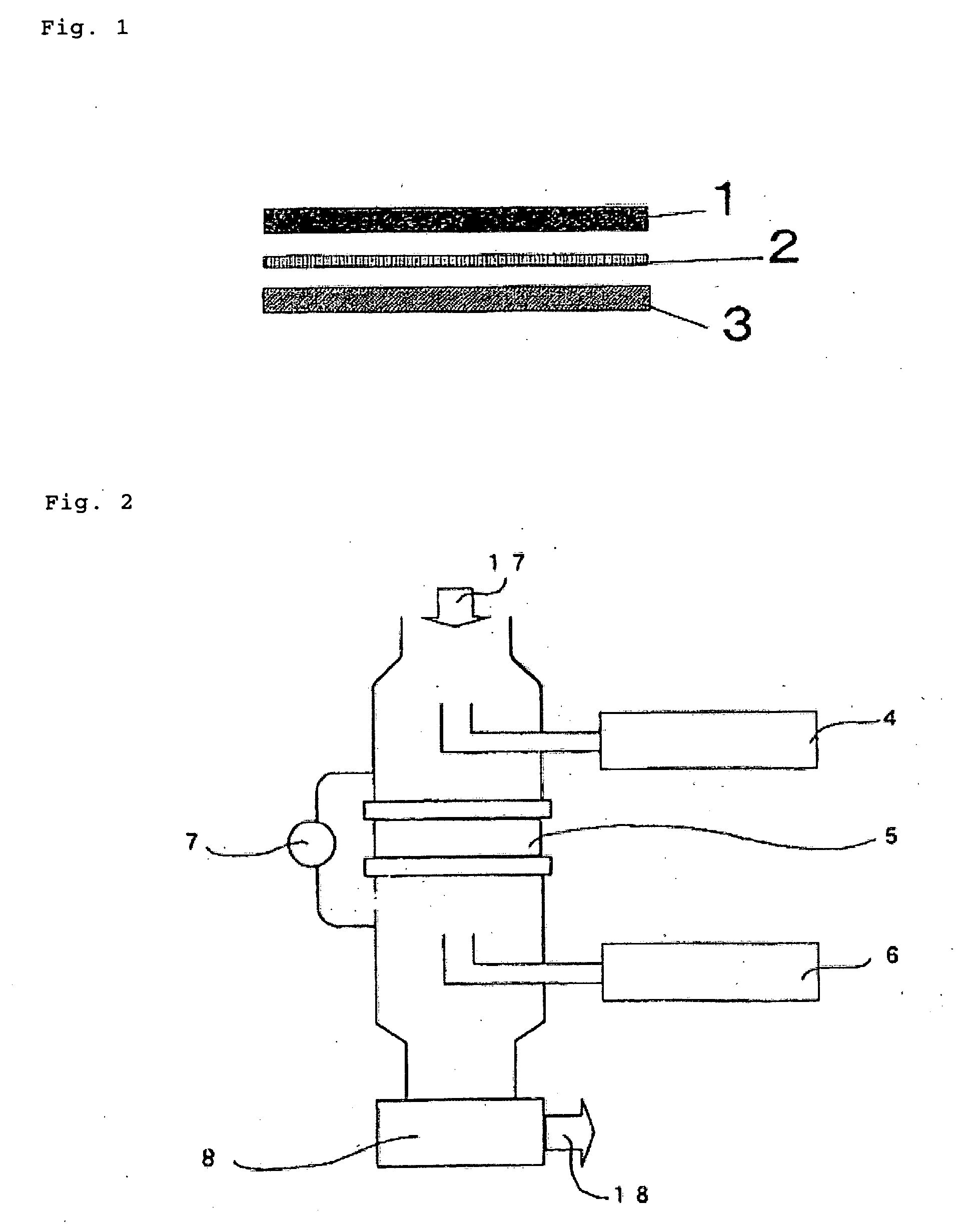
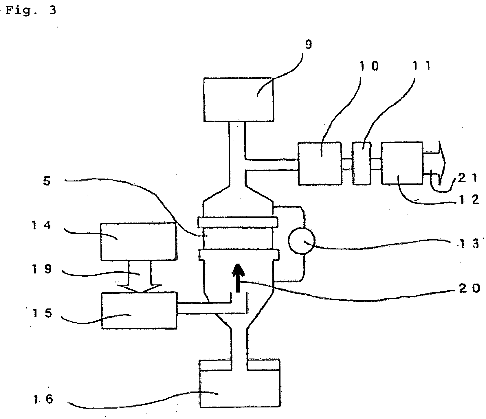

Image

  • Filter medium
  • Filter medium
  • Filter medium

Examples


example 1

[0119] PPS staple fibers with a fineness of 3.0 dtex (fiber diameter 17 μm) and a cut length of 76 mm (“TORCON®” S101-3.0T76 mm, produced by Toray Industries, Inc.) were used to obtain a spun yarn (total fineness 600 dtex) having a single yarn count of 20 s obtained by doubling two yarns. Yarns, each produced as above, were used to form a PPS spun yarn plain weave fabric with a warp density of 26 threads / 2.54 cm and a weft density of 18 threads / 2.54 cm. The woven fabric was used as the scrim. Meanwhile, PPS staple fibers with a fineness of 2.2 dtex (fiber diameter 14.5 μm) and a cut length of 51 mm (“TORCON®” S101-2.2T51 mm, produced by Toray Industries, Inc.) and PPS staple fibers with a fineness of 1.0 dtex (fiber diameter 9.7 μm) and a cut length of 51 mm (“TORCON®” S101-1.0T51 mm, produced by Toray Industries, Inc.) were blended at a ratio by weight of 50:50, and the blended staple fibers were treated using an opener and a carding machine, and temporarily needle-punched at a nee...

example 2

[0120] PPS staple fibers with a fineness of 1.0 dtex (fiber diameter 9.7 μm) and a cut length of 51 mm, PPS staple fibers with a fineness of 2.2 dtex (fiber diameter 14.5 μm) and a cut length of 51 mm, and PPS staple fibers with a fineness of 7.8 dtex (fiber diameter 27.2 μm) and a cut length of 51 mm were blended at 30:30:40, for being used as the fibers constituting the web on the dust side. Furthermore, PPS staple fibers with a fineness of 2.2 dtex and a cut length of 51 mm and PPS staple fibers with a fineness of 7.8 dtex and a cut length of 51 mm were blended at 50:50 for being used as the fibers constituting the web on the clean side. A filter fabric was obtained by the same method as described for Example 1, except that the above webs were used. The performance of the obtained filter fabric is shown in Table 1 and FIGS. 4 and 5.

example 3

[0121] A filter fabric was obtained by the same method as described for Example 1, except that PPS staple fibers with a fineness of 1.0 dtex (fiber diameter 9.7 μm) and a cut length of 51 mm and PPS staple fibers with a fineness of 2.2 dtex (fiber diameter 14.5 μm) and a cut length of 51 mm were blended for being used as the fibers constituting the web on the dust side. The performance of the obtained filter fabric is shown in Table 1 and FIGS. 4 and 5.


PUM

PropertyMeasurementUnit
diameteraaaaaaaaaa
diameteraaaaaaaaaa
diameteraaaaaaaaaa

Abstract

The filter fabric containing polyphenylene sulfide fibers, characterized in that the following (1) and / or (2) is satisfied is used to provide a filter fabric and a bag filter composed of the filter fabric excellent in dust-collecting efficiency and high in mechanical strength: (1) Containing at least two webs, one of which on the dust side contains 50 wt % or more of heat resistant fibers with a fiber, diameter of 15 μm or less, while the other web on the clean side contains 50 wt % or more of heat resistant fibers with a fiber diameter of 20 μm or more (2) Containing a web containing polyphenylene sulfide staple fibers with their fineness kept in a range from 1 to 3 dtex and fluorine-based staple fibers with their fineness kept in a range from 2 to 4 dtex.

Description

TECHNICAL FIELD [0001] The present invention relates to a filter fabric that can function to collect and remove contaminants such as dust in air for cleaning the air. The filter fabric of this invention can be suitably used as a dust-collecting filter cloth for filtering the high temperature exhaust gases emitted from refuse incinerators, coal boilers, metal blast furnaces and the like, and also as a bag filter produced by sewing said filter cloth. BACKGROUND ART [0002] Filter fabrics used for cleaning air include filter fabrics for depth filtration and filter fabrics for surface filtration, and dust collectors use the filter fabrics for surface filtration. In the case of surface filtration, dust is collected on the surface of a filter fabric, to form a dust layer on the surface of the filter fabric, and dust is successively collected by the dust layer. When the dust layer grows to have a certain thickness, it is removed from the surface of the filter fabric by means of air pressure...

Claims


Application Information

Patent Timeline
Patent Type & Authority Applications(United States)
IPC IPC(8): B32B5/02B01D39/14B01D39/16B01D39/20D04H1/4326D04H1/4374
CPCB01D39/1623B01D39/2017B01D2239/0457B01D2239/0613B01D2239/064B01D2239/0654B01D2239/0659B01D2239/1233Y10T442/696Y10T442/107Y10T442/20Y10T442/2861Y10T442/3472Y10T442/102Y10T442/2631Y02A50/2351
Inventor YAMADA, KENKONAGASE, MOTOKI
Owner TORAY IND INC
Learn More