
Enameled wire having magnetic reluctance properties and preparation method thereof, and coil using the same and preparation method thereof

a technology of enameled wire and magnetic resistance, which is applied in the direction of insulated conductors, cables, conductors, etc., can solve problems such as energy loss, and achieve the effects of reducing resistance and load of wires, reducing energy loss, and inhibiting temperature ris

Inactive Publication Date: 2006-07-27
WEDO
View PDF1 Cites 23 Cited by
  • Summary
  • Abstract
  • Description
  • Claims
  • Application Information

AI Technical Summary

Benefits of technology

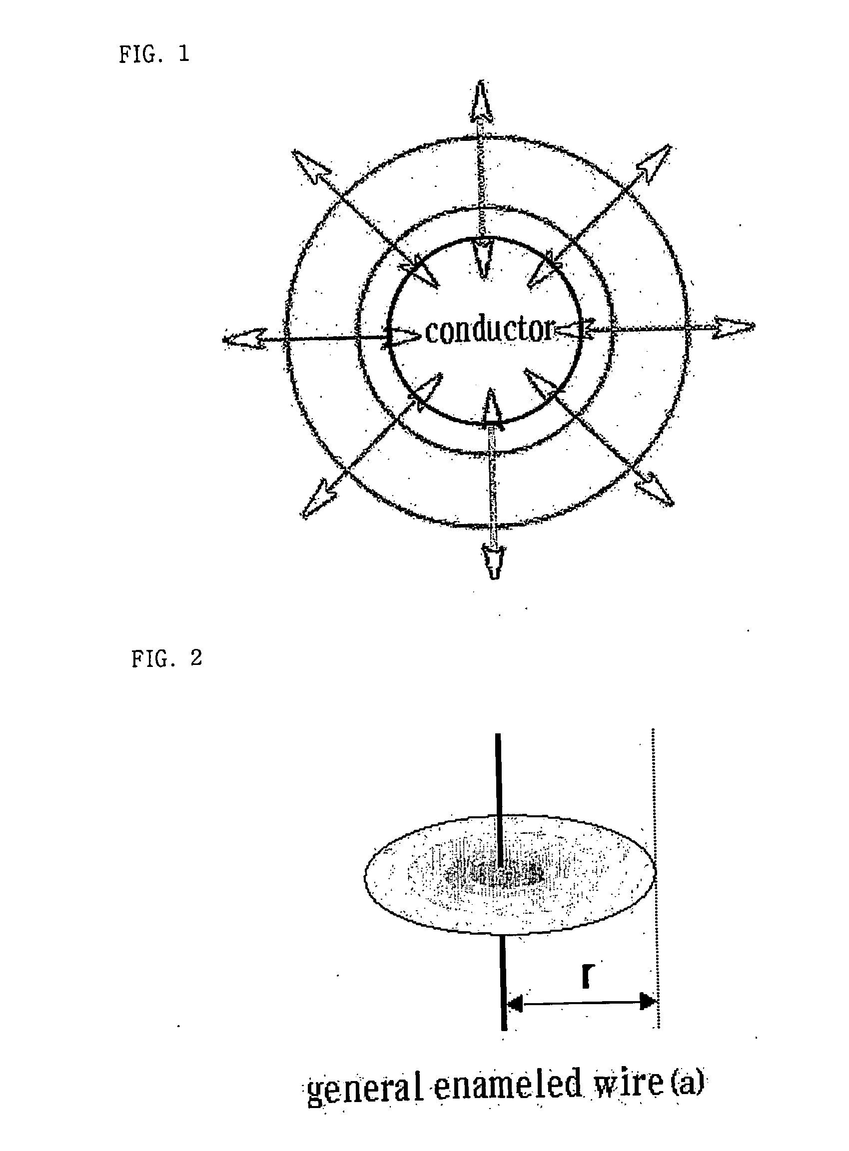
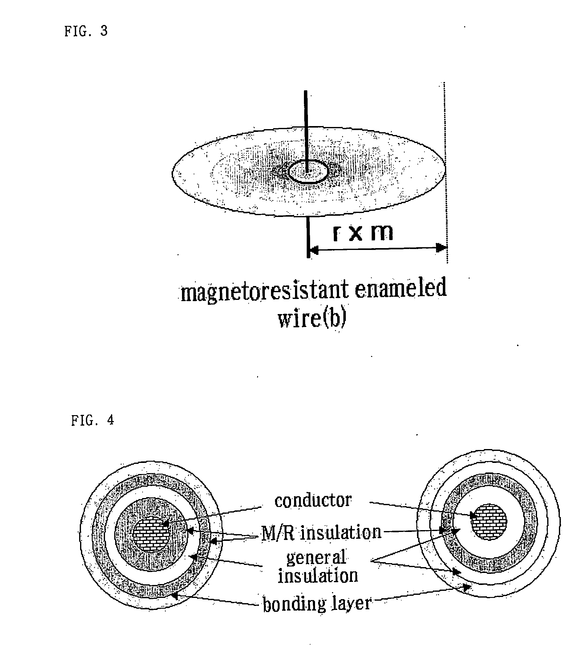
[0022] It is an object of the present invention to provide a magnetoresistant enameled wire, a manufacturing method thereof, a magnetoresistant coil using the magnetoresistant wire, and a manufacturing method of the magnetoresistant coil, that are capable of minimizing the energy loss as well as inhibiting temperature rise by reducing the resistance and load of the wire during the energy transfer thereon.
[0023] It is another object of the present invention to provide a magnetoresistant enameled wire, a manufacturing method thereof, a magnetoresistant coil using the magnetoresistant wire, and a manufacturing method of the magnetoresistant coil, that are capable of obtaining high exterior magnetic flux density
[0024] It is still another object of the present invention to provide a magnetoresistant enameled wire, a manufacturing method thereof, a magnetoresistant coil using the magnetoresistant wire, and a manufacturing method of the magnetoresistant coil, that are capable of preventing the isolation from being easily damaged.
[0025] It is still another object of the present invention to provide a magnetoresistant enameled wire, a manufacturing method thereof, a magnetoresistant coil using the magnetoresistant wire, and a manufacturing method of the magnetoresistant coil, that are capable of giving an effect similar to the anisotropic magnetoresistance even at low voltage.

Problems solved by technology

As described above, the conventional enameled wire has drawbacks in that there is no solution for inhibiting the heat generation caused by the resistance of the wire itself, resulting in energy loss.

Method used


Image

  • Enameled wire having magnetic reluctance properties and preparation method thereof, and coil using the same and preparation method thereof
  • Enameled wire having magnetic reluctance properties and preparation method thereof, and coil using the same and preparation method thereof

Examples


example 1

[0167] (Preparation of Polyester-Based Magnetically Soft Varnish)

[0168] 1.225 parts by weight of a magnetically soft material of a composite oxide containing about 63% of FeO, about 23% of FeO, about 9% of CoFeO as main components, and 0.125 parts by weight of a polyethylene polymeric protective colloid-based dispersing agent were added to 100 parts by weight of the general polyester-based insulating varnish prepared in Comparative Example 1. The mixture was stirred and dispersed to prepare a polyester-based varnish containing a magnetically soft material. The varnish thus prepared had a degree of softening degree of 4.

[0169] (Manufacture of Polyester-Based Magnetically Soft Varnish-Coated Enameled Wire)

[0170] A magnetically soft material-type enameled wire was manufactured in the same manner as in Comparative Example 1, except that the polyester-based magnetically soft varnish was coated instead of the general polyester-based insulating varnish. The thickness of the varnish laye...

example 2

[0176] (Preparation of Polyvinylformal-Based Magnetically Soft Varnish)

[0177] 1.10 parts by weight of a magnetically soft material of a composite oxide containing about 63% of FeO, about 23% of FeO, about 9% of CoFeO as main components, and 0.05 parts by weight of a fatty acid polyamide-based dispersing agent were added to 100 parts by weight of the general polyvinylformal-based insulating varnish prepared in Comparative Example 2. The mixture was stirred and dispersed to prepare a polyvinylformal-based varnish containing a magnetically soft material. The varnish thus prepared had a degree of softening of 4.

[0178] (Manufacture of Polyvinylformal-Based Magnetically Soft Varnish-Coated Enameled Wire)

[0179] A magnetoresistant enameled wire was manufactured in the same manner as in Comparative Example 2, except that the polyvinylformal-based magnetically soft varnish was coated instead of the general polyvinylformal-based insulating varnish.

[0180] The thickness of the magnetically s...

example 3

[0186] (Preparation of Polyurethane-Based Magnetically Soft Varnish)

[0187] 1.20 parts by weight of a magnetically soft material of a composite oxide containing about 63% of FeO, about 23% of FeO, about 9% of CoFeO as main components, and 0.15 parts by weight of a fatty acid amide-based dispersing agent were added to 100 parts by weight of the general polyurethane-based insulating varnish prepared in Comparative Example 3. The mixture was stirred and dispersed to prepare a polyurethane-based magnetically soft varnish. The varnish thus prepared had a degree of softening of 4.

[0188] (Manufacture of Polyurethane-Based Magnetically Soft Varnish-Coated Enameled Wire)

[0189] A magnetically soft enameled wire was manufactured in the same manner as in Comparative Example 3, except that the polyurethane-based magnetically soft varnish was coated instead of the general polyurethane-based insulating varnish.

[0190] The thickness of the varnish layer of the enameled wire thus manufactured was ...


PUM

PropertyMeasurementUnit
temperatureaaaaaaaaaa
thicknessaaaaaaaaaa

Abstract

Disclosed herein is a magnetoresistant enameled wire coated with a material which shows improved conductivity by reducing resistance of a conductor since the wire exhibits effects similar to anisotropic magnetoresistance of magnetic materials when manufactured in the form of a coil. The material also shows effects similar to magnetoresistance exhibiting a strong magnetic flux density. Disclosed further are a method for manufacturing the magnetoresistant enameled wire, a magnetoresistant coil using the magnetoresistant wire, and a method for manufacturing the magnetoresistant coil.

Description

TECHNICAL FIELD [0001] The present invention relates to a magnetoresistant enameled wire, and more particularly to a magnetoresistant enameled wire, a method for manufacturing the magnetoresistant enameled wire, a magnetoresistant coil using the magnetoresistant wire, and a method for manufacturing the magnetoresistant coil, the magnetoresistant enameled wire showing improved conductivity by reducing resistance of a conductor since the wire exhibits effects similar to anisotropic magnetoresistance or tunneling magnetoresistance when it is manufactured in the form of a coil, and externally exhibiting a strong magnetic flux density. BACKGROUND ART [0002] Typically, used with electric appliances, communication equipments, sound equipments, etc., are coils manufactured by winding an insulated wire around a supporting tube and insulating varnish thereon so as to stick to and close fit the windings each other or manufactured by coating a self-bonding varnish on the insulated wire instead ...

Claims


Application Information

Patent Timeline
Patent Type & Authority Applications(United States)
IPC IPC(8): D02G3/00H01B7/00H01F27/00H01B7/02H01B13/00H01F5/00
CPCH01B7/0009Y10T428/2933H01F5/00H01B7/0208
Inventor YOON, JONGO
Owner WEDO
Learn More