
Method for producing optical sheet, optical sheet, and method for producing lenticular lens sheet

a manufacturing method and technology for lenticular lenses, applied in the field of manufacturing methods for lenticular lenses, can solve the problems of high thickness accuracy, difficult to produce thin sheets having such shapes, and inability to achieve such thickness distribution, etc., to achieve high thickness accuracy, low manufacturing cost, and high shaping/transfer performance

Inactive Publication Date: 2006-07-06
KURARAY CO LTD
View PDF1 Cites 23 Cited by
  • Summary
  • Abstract
  • Description
  • Claims
  • Application Information

AI Technical Summary

Benefits of technology

[0023] The present invention provides a manufacturing method for an optical sheet for passing a thermoplastic resin discharged from a die between a touch roll and a shaping roll under pressure to manufacture an optical sheet, wherein a temperature of the resin discharged from the die is in a range of 2500 to 290° C., a molding speed is in a range of 8 to 40 m / min., and an air gap between the die and a nip position between the touch roll and the shaping roll is 110 mm or smaller. The touch roll is an elastic roll deformable in a diameter direction by 0.01% or more of a diameter under a linear pressure of 30 kg / cm. According to the manufacturing method, a thin optical sheet of a uniform thickness distribution can be formed with a high thickness accuracy, and high shape and transfer fidelity.
[0028] The present invention provides a manufacturing method for a lenticular lens sheet, including: a step of forming a lenticular lens sheet having a thickness of 350 μm or less through extrusion molding; a step of forming a photosensitive layer on a flat surface of the lenticular lens sheet; and a step of forming a light-shielding pattern by irradiating the photosensitive layer with light from a lenticular lens side of the lenticular lens sheet to form a cured portion and an uncured portion by use of light focused through the lenticular lens. According to the manufacturing method, a low-cost, high-quality lens sheet can be formed.
[0031] Further, the lenticular lens sheet is manufactured passing a thermoplastic resin discharged from a die between a touch roll and a shaping roll under pressure, in the step of forming the lenticular lens sheet, a temperature of the resin discharged from the die is in a range of to 250° to 290° C., a molding speed is in a range of to 8 to 40 m / min., an air gap between the die and a nip position between the touch roll and the shaping roll is 110 mm or smaller, and the touch roll is an elastic roll deformable in a diameter direction by 0.01% or more of a diameter under a linear pressure of 30 kg / cm. According to the manufacturing method, a thin optical sheet of a uniform thickness distribution can be formed with a high thickness accuracy, and high shaping / transferring performances.
[0032] A lens sheet according to the present invention is manufactured by using the manufacturing method for a lens sheet. The lens sheet thus manufactured costs low, and attains high quality.

Problems solved by technology

However, with the manufacturing method based on the extrusion molding, it is difficult to produce a thin sheet having such a shape that gives an optical performance sufficient for optical use, with a high thickness accuracy.
This is because the contact between a roll and a resin gets worse owing to an unbalanced relation between a resin pressure and a pressing force / rigidity of a roll, which causes the roll to deform on the thin sheet requiring a high thickness accuracy, and the deformed roll cannot press the central portion of the sheet, making it impossible to attain such a thickness distribution that realizes the uniform optical performance.
To that end, the roll hardly produces an optical functional sheet with a shaping rate and transfer accuracy high enough for optical usage.
Further, there have not been made extensive efforts to transfer a desired lens shape with the method of manufacturing a smooth sheet using this elastic roll based on the common belief that the resin is cooled and solidified on contact with a mold roll, and sufficient transferability cannot be achieved unless the resin is applied with enough pressure upon molding.
In particular, conventional manufacturing methods for an optical sheet hardly produce an optical sheet satisfying all of conditions such as the thickness of 300 μm or smaller, a pitch of 300 μm or smaller, and the mold height of 30 μm or larger.
With the aforementioned manufacturing methods for an optical sheet, the shape that gives an optical performance can be transferred with the use of a rigid roll, but a thin film of a uniform thickness distribution is difficult to form with a high thickness accuracy.
A thin sheet of a uniform thickness distribution can be produced with a high thickness accuracy by use of an elastic roll, but it is impossible to attain shaping / transferring performances enough for optical use.
As a result, the high thickness accuracy for the optical sheet and the high shaping / transferring performances could not be both fulfilled at the same time.
In manufacturing the lenticular lens sheet 102 using the 2P resin in the above manner, there arises a problem of an increase in production cost for a rear projection screen due to the expensive 2P resin.
There is another problem in that the productive facility for the lenticular lens sheet 102 is complicated because the transparent supporting member 1022 is formed and then, the lens portion 1021 is formed thereon.
Moreover, in the case of using the 2P resin, the lens portion 1021 differs from the transparent supporting member 1022 in material, which leads to poor environmental stability, and causes a lenticular lens sheet 1 to warp.
The difference in refractive index between them causes color unevenness or limits the transparency in some cases.
Further, since the lens portion 1021 and the transparent supporting member 1022 are different in material, edge blunting easily occurs, and there is a limitation on the shaping performance.
As mentioned above, with the conventional manufacturing methods for an optical sheet, the shape that gives an optical performance can be transferred with the use of a rigid roll, but a thin film of a uniform thickness distribution is difficult to form with a high thickness accuracy.
A thin sheet of a uniform thickness distribution can be produced with a high thickness accuracy by use of an elastic roll, but it is impossible to attain shaping / transferring performances enough for optical use.
As a result, the high thickness accuracy for the optical sheet and the high shaping / transferring performances could not be both fulfilled at the same time.
Besides, the conventional manufacturing method for the lenticular lens sheet has a problem that two different materials are used and therefore, a low-cost, high-quality lenticular lens sheet cannot be formed.

Method used


Image

  • Method for producing optical sheet, optical sheet, and method for producing lenticular lens sheet
  • Method for producing optical sheet, optical sheet, and method for producing lenticular lens sheet
  • Method for producing optical sheet, optical sheet, and method for producing lenticular lens sheet

Examples


first embodiment

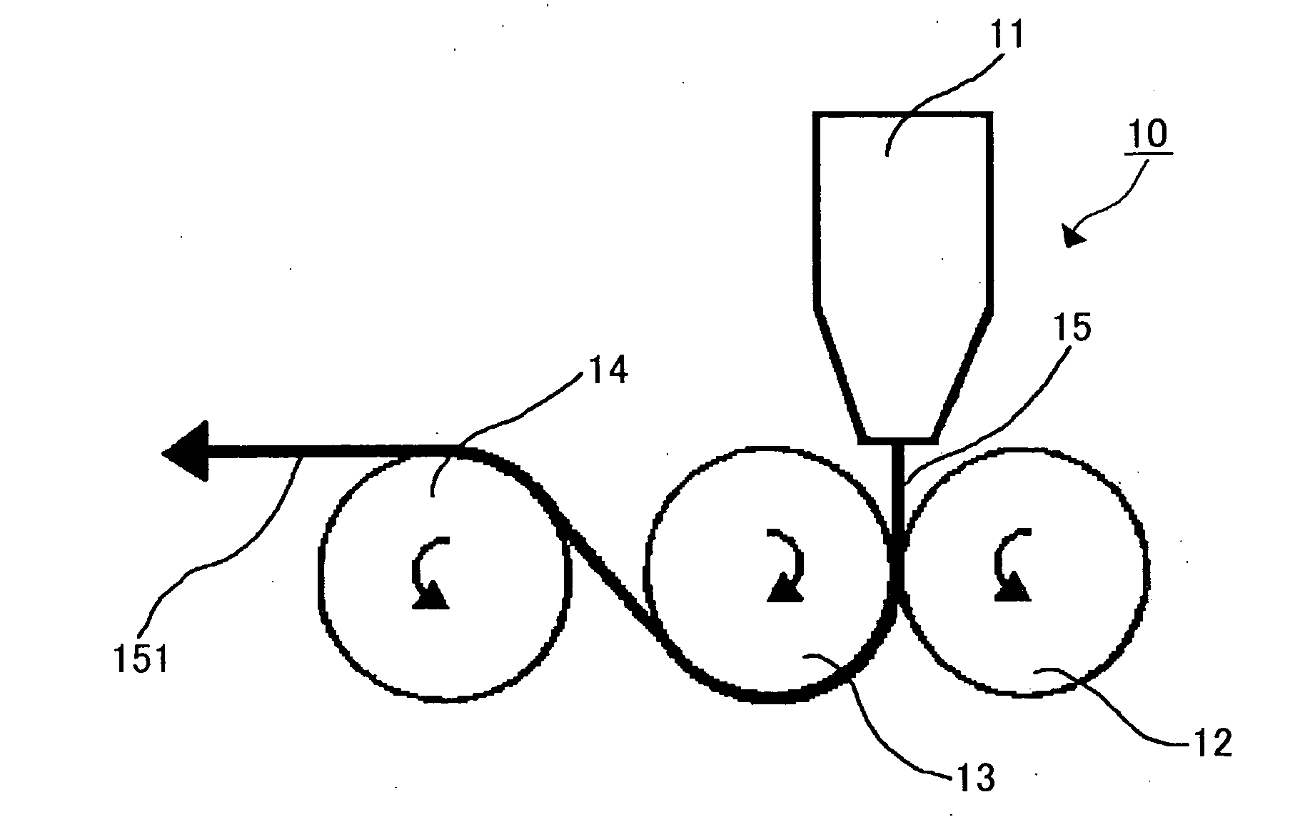
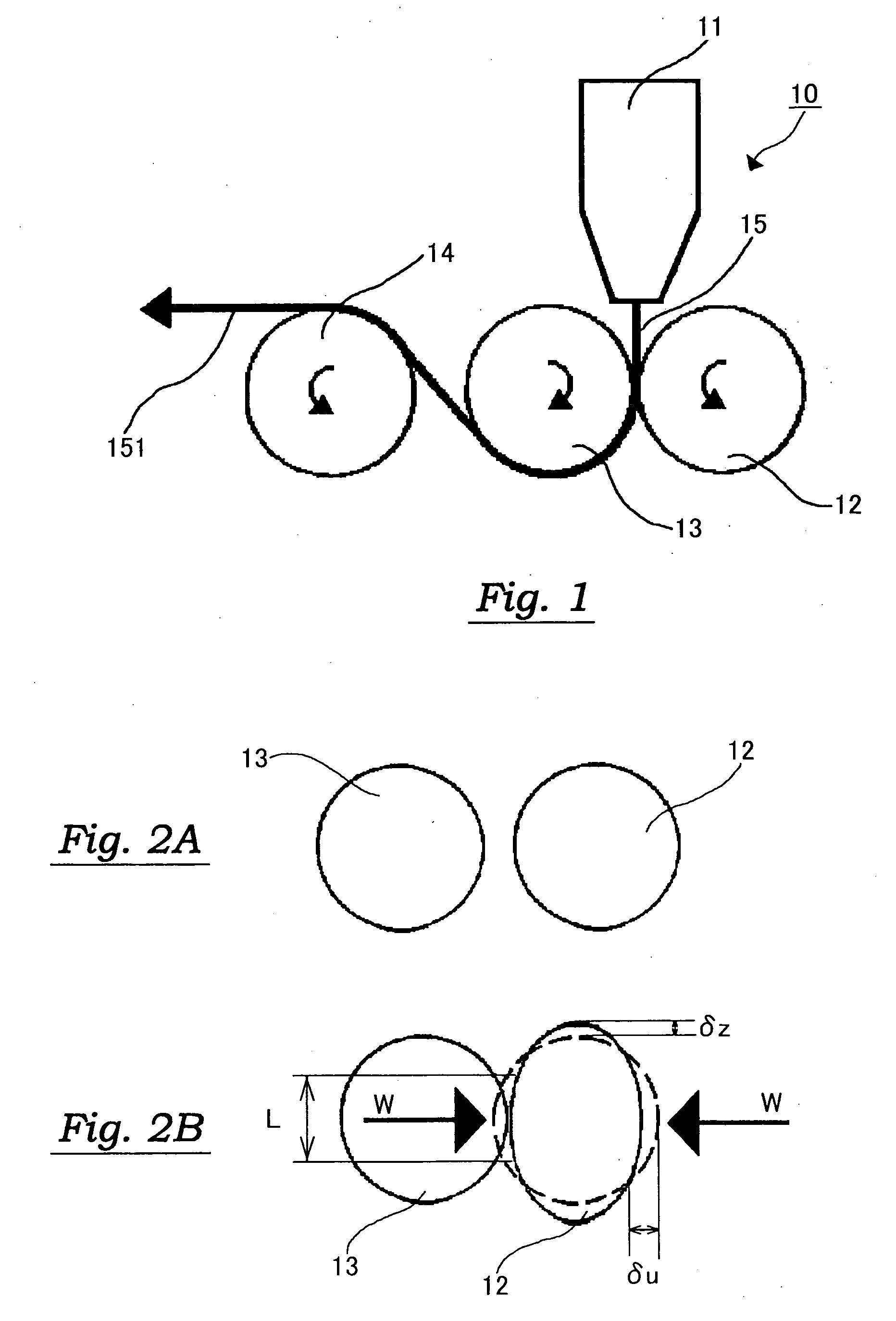
[0047] Referring now to FIG. 1, a manufacturing method for a lenticular lens sheet is described first. FIG. 1 is a sectional view showing a manufacturing apparatus for a lenticular lens sheet.

[0048] As shown in FIG. 1, a lenticular lens sheet manufacturing apparatus 10 includes a die 11, a first roll 12, a second roll 13, and a third roll 14.

[0049] The die 11 is a discharging member for discharging a resin 15 in a molten form by use of an extruder. A temperature of the resin 15 discharged from the die 11 preferably exceeds 230° C., more specifically, ranges from 250° C. to 290° C. With the resin temperature below 230° C., the melt viscosity of the resin is too high, leading to insufficient transferability of a shaping roll in some cases. In contrast, the resin temperature above 290° C. may accelerate thermal decomposition of the resin, resulting in a discolored and whitish resin.

[0050] The first roll 12 is a touch roll for pressing the molten resin 15 against the second roll 13. ...

second embodiment

[0078] When an elastic metal roll exhibiting an elastic behavior is used as the first roll 12, any optical sheet embossed on both sides can be formed by engraving a given shaping pattern on the first roll 12 as well.

[0079] Besides, the degree of freedom in design of an optical pattern to be transferred can be enhanced by attaching a mold plate around the second roll 13 by means of an adhesive. In addition, the heat insulating property of the second roll 13 can be improved, and an optical function sheet can be formed with the high thickness accuracy, high transferability, and the like.

third embodiment

[0080] In a third embodiment, a description is given of an overall process of a manufacturing method for a lens sheet according to this embodiment with reference to FIG. 4. FIG. 4 is a schematic diagram showing a structural example of an entire lens sheet manufacturing apparatus.

[0081] In FIG. 4, reference numeral 10 denotes the lenticular lens sheet manufacturing apparatus; 11, the die; 110, an extruder; 12, the first roll; 13, the second roll; 14, the third roll; 140, a fourth roll; and 141 and 142, conveying rolls. As mentioned below, an elastic roll is used as the first roll 12.

[0082] The lenticular lens sheet manufacturing apparatus 10 mainly carries out the following extrusion-molding step. To elaborate, the die 11 first discharges the molten rein 15 by means of the extruder 110 to the air gap between the first roll 12 and the second roll 13. The discharged resin 15 is pressed against the second roll 13 by the first roll 12. At this time, the second roll 13 transfers the opt...


PUM

PropertyMeasurementUnit
Temperatureaaaaaaaaaa
Fractionaaaaaaaaaa
Fractionaaaaaaaaaa

Abstract

The present invention aims at providing a manufacturing method for an optical sheet capable of manufacturing a thin optical sheet of a uniform thickness distribution with a high thickness accuracy, and high shaping / transferring performances, and an optical sheet manufactured by using the manufacturing method. A manufacturing method for an optical sheet according to the present invention includes passing a resin discharged from a die between a touch roll and a shaping roll under pressure.

Description

TECHNICAL FIELD [0001] The present invention relates to a manufacturing method for an optical sheet, an optical sheet, and a manufacturing method for a lenticular lens sheet. BACKGROUND ART [0002] In conventional manufacturing methods for an optical sheet, a sheet resin material extruded from an extrusion die is passed under pressure through a gap between a pair of engraved roll and mirror-finished metal roll to manufacture a resin sheet. With such a manufacturing method, it is necessary to use a rigid roll with the pressing force allowing some uniform sheet thickness to manufacture a sheet with any optical performance. It is also necessary to transfer a reverse pattern engraved on a mold roll onto a sheet to create the smooth surface or particular surface shape as is necessary for exhibiting an optical performance, at some shaping rate. [0003] In recent years, there is a growing demand for thinner optical sheets in response to needs to downsize the lens to shorten a focal distance ...

Claims


Application Information

Patent Timeline
IPC IPC(8): B29D11/00B29C43/22B29C48/08
CPCB29C43/222B29C47/0021B29C47/886B29D11/00278B29C48/08B29C48/914B29C48/9155B29C48/906G02B3/00G03B21/60
Inventor BABA, KAZUOHIROSE, KAZUNORINAKAZATO, ETSUOMATSUZAKI, ICHIRO
Owner KURARAY CO LTD
Learn More