
Flight lock actuator with dual energy sources

a dual-energy source, actuator technology, applied in the field of actuators, can solve the problems of actuator failure, mechanical occasional failure of the actuator, so as to reduce mechanical shock, prevent motor damage from overheating, and effectively braking the actuator

Inactive Publication Date: 2006-06-29
WHIPPANY ACTUATION SYST
View PDF9 Cites 8 Cited by
  • Summary
  • Abstract
  • Description
  • Claims
  • Application Information

AI Technical Summary

Benefits of technology

[0008] A motor control system is provided that senses the rotational speed of the flight lock actuator motor, and which limits both the retract and extend strokes to a desired maximum velocity to reduce mechanical shock. The motor control system also limits, to a desired maximum, the current supplied to the actuator motor during a period of powered stall to prevent motor damage from overheating. The motor control system also includes a damper feature that is capable of effectively braking the actuator during a back-driven extension stroke to ensure a controlled arrival into the extended position mechanical stop.

Problems solved by technology

Actuators built according to the present art suffer occasional failure due to damage from abruptly impacting mechanical stops at the end of an actuator's stroke, especially while being back-driven by a spring system during the unpowered extension stroke to the unlocked position.
These repeated mechanical shocks to the internal mechanism of a flight lock actuator can cause jamming and mechanical failure of the actuator.
In addition, actuator failure may also result from damage to a brush-type actuator motor due to prolonged periods of powered stall in the locked position.

Method used


Image

  • Flight lock actuator with dual energy sources
  • Flight lock actuator with dual energy sources
  • Flight lock actuator with dual energy sources

Examples


Embodiment Construction

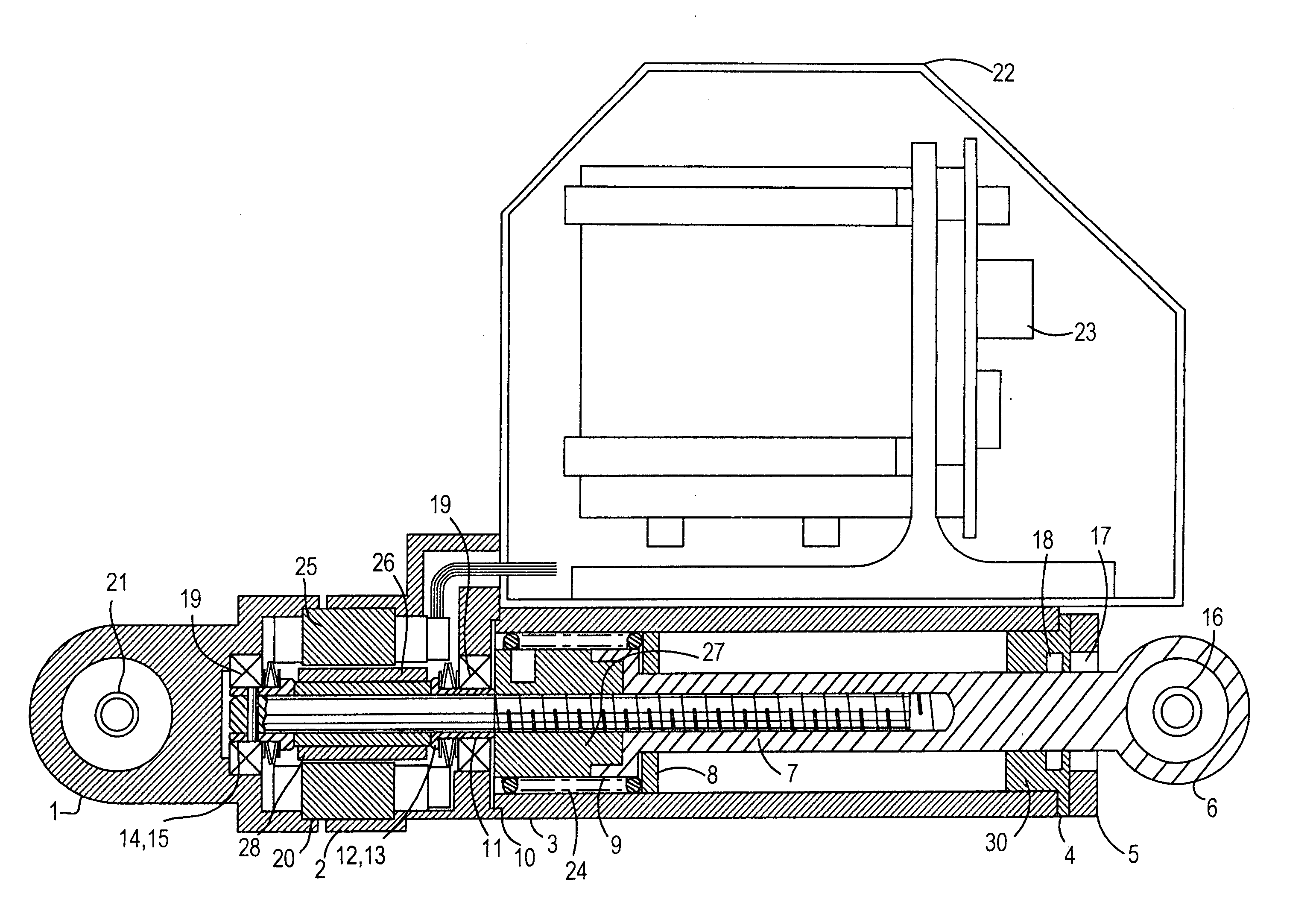
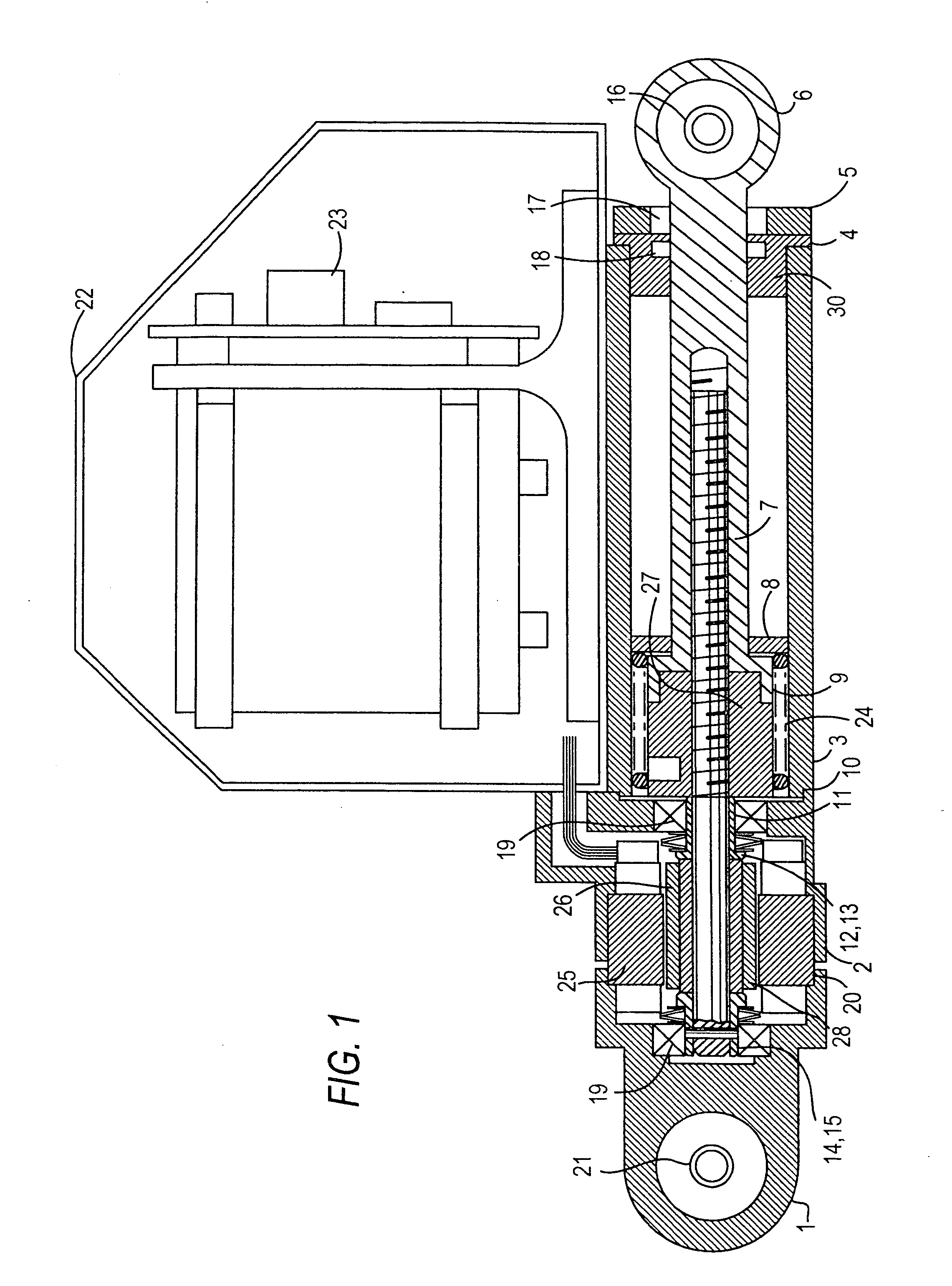
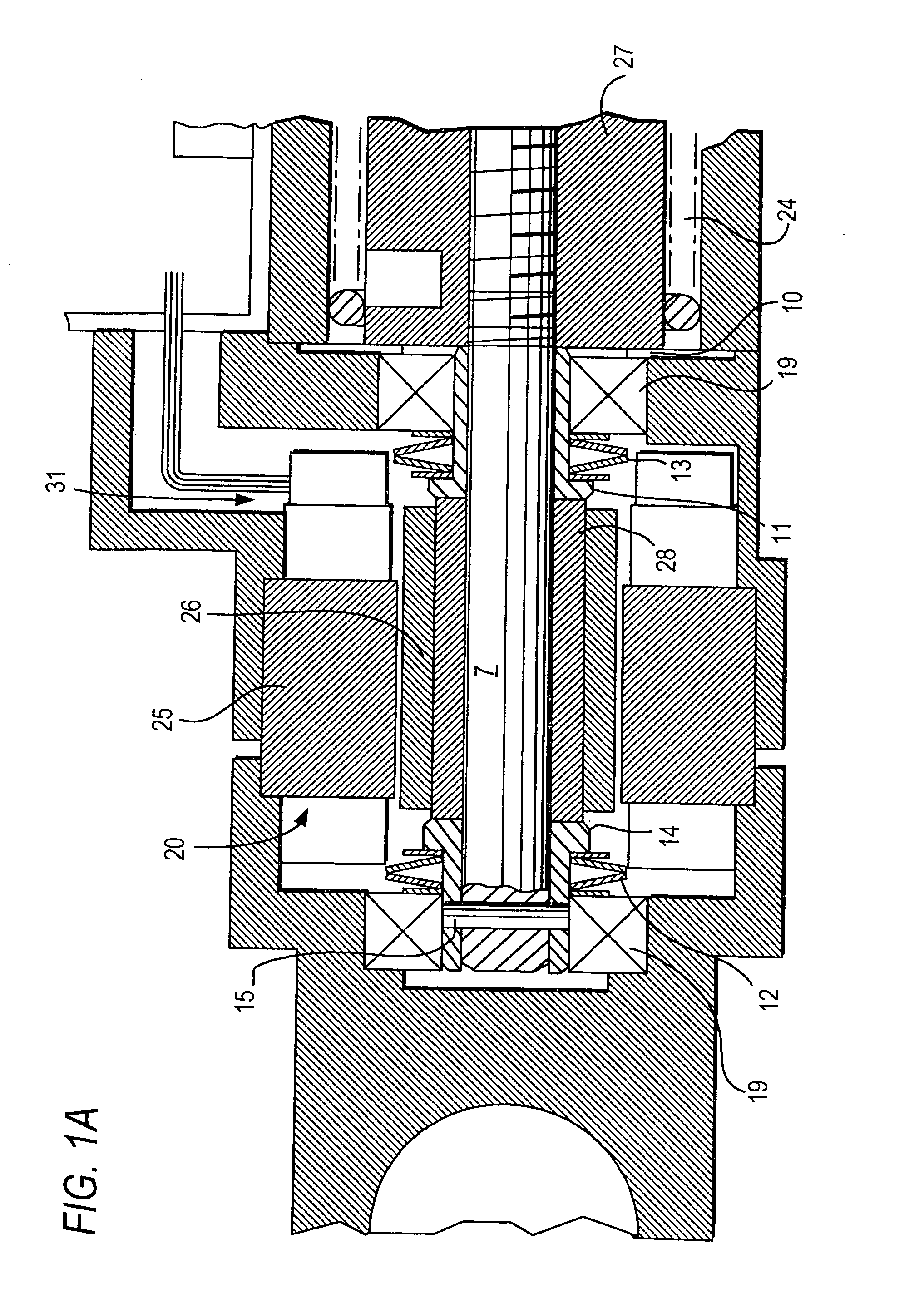
[0013] As shown in FIGS. 1 and 1A, an illustrative embodiment of the flight lock actuator mechanical system includes rear housing 1, center housing 2, guide tube 3, guide bushing 4, and front cover 5. Disposed within rear housing 1 and center housing 2 is a brushless DC electric motor 20, which includes stator 25 and rotor 26. Rotor 26 includes rotor shaft 28, which rotates with rotor 26. Ball screw shaft 7 is press fit into rotor shaft 28, so that ball screw shaft 7 also rotates with rotor 26. The right-hand portion of ball screw shaft 7 is threaded to provide the central element of a ball screw assembly. Ball screw shaft 7 is axially and rotationally fixed to sleeve 14. Pin 15 is captured within the inner race of bearing 19, and extends diametrically through shaft 7 and sleeve 14 to ensure the fixed relationship between elements 7 and 14.

[0014] The rotational assembly including rotor 26, shaft 7, and sleeve 14 is rotatably supported by bearings 19. Sleeves 11 and 14 are slidable ...


PUM


Abstract

A flight lock actuator that can be powered by two sources of stored energy when aircraft power has been switched off. A mechanical energy storage means and an electrical energy storage means provide a fully redundant energy storage system that stores sufficient energy to complete the actuator's extension stroke when aircraft power is removed. The actuator has a motor control system that limits the stroke velocity for both the extension and retraction strokes, including a damper feature capable of effectively braking the actuator during the back-driven extension stroke.

Description

CROSS REFERENCE TO RELATED APPLICATIONS [0001] This application is a divisional of U.S. patent application Ser. No. 10 / 260,470, filed Sep. 26, 2002, which claims priority from U.S. provisional application No. 60 / 348,881, filed Nov. 13, 2001, both of which are hereby incorporated by reference herein in their entireties.BACKGROUND OF THE INVENTION [0002] This invention relates to actuators used in aircraft door lock mechanisms. More specifically, this invention relates to systems and methods for improving the reliability of aircraft door flight lock actuators. Flight lock actuators are used in aircraft door lock mechanisms to secure a lock mechanism in the locked position during flight, or whenever aircraft power is supplied to the actuator. During flight, for safety reasons, it is conventional practice to maintain the flight lock actuator in a powered stall against its locked position stop. When aircraft power is removed at the end of the flight, the flight lock actuator is conventio...

Claims


Application Information

Patent Timeline
IPC IPC(8): B64C1/14E05B65/12H02K7/06
CPCB64C1/1407E05B81/25E05B2047/0023H02K7/06
Inventor BARBA, VALENTIN G.
Owner WHIPPANY ACTUATION SYST
Learn More