
Transmission device with stepless speed regulating function

A transmission device, stepless speed regulation technology, applied in the directions of transportation and packaging, conveyors, fluid clutches, etc., can solve the problem of increasing the construction cost of equipment foundation, increasing the amount of roadway engineering, and increasing the space occupied by the drive part of the belt conveyor. Large and other problems, to achieve the effect of saving space, reducing volume and footprint, and reducing impact

Inactive Publication Date: 2014-07-23
SHANDONG UNIV OF SCI & TECH
View PDF6 Cites 5 Cited by
  • Summary
  • Abstract
  • Description
  • Claims
  • Application Information

AI Technical Summary

Problems solved by technology

However, installing a speed regulating device between the motor and the reducer will increase the space occupied by the driving part of the belt conveyor, which is difficult to meet in some applications with limited space, such as underground coal mines.
Excessively large space will increase the engineering volume of roadway and chamber development, and also increase the cost of equipment foundation construction

Method used


Image

  • Transmission device with stepless speed regulating function
  • Transmission device with stepless speed regulating function
  • Transmission device with stepless speed regulating function

Examples


Embodiment Construction

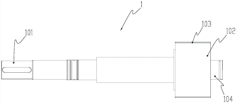
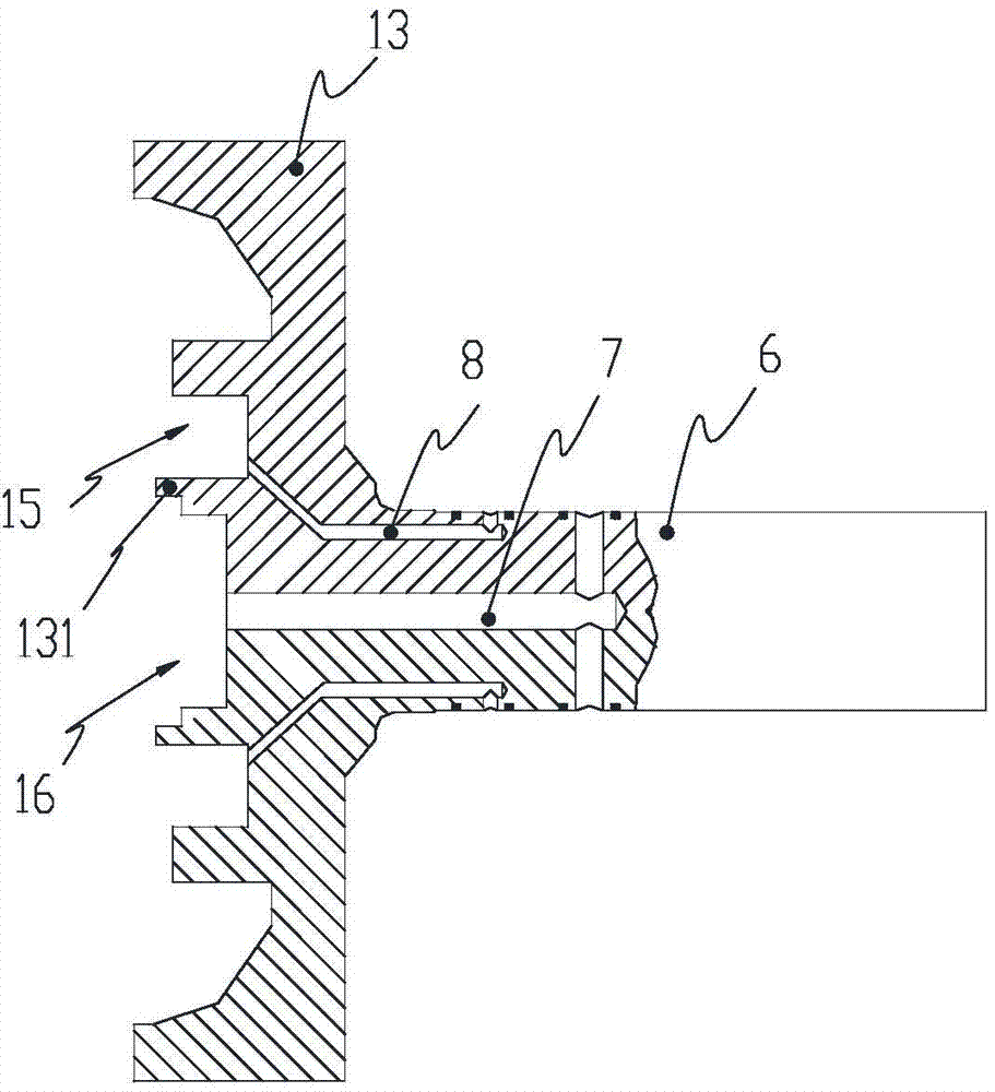
[0023] to combine Figure 1 to Figure 6 , a transmission device with stepless speed regulation function, including a drum 11 , a power input shaft 1 and a drum end shaft 6 . The outer end 101 of the above-mentioned power input shaft is located on one side of the drum, and the inner end 102 of the power input shaft extends into the inner cavity of the drum until it is close to the other side of the drum. The power input shaft is installed on the first drum through the end cover bearing 3 and the sealing ring. On the end cover 12, the power input shaft and the first end cover of the drum are in a dynamic sealing connection, the first end cover of the drum is fixed on one side of the drum, and the first end cover of the drum and the drum are in a sealed connection. The above-mentioned drum end shaft is fixed on the other side of the drum through the second end cover 13 of the drum. The second end cover of the drum and the drum are in a sealed connection. The end shaft 6 of the dr...


PUM


Abstract

The invention discloses a transmission device with a stepless speed regulating function. The transmission device is characterized by comprising a roller, a power input shaft and a roller end shaft, wherein the outer end of the power input shaft is located on one side of the roller, the inner end of the power input shaft stretches into an inner cavity of the roller until being close to the other side of the roller, the power input shaft is arranged on a roller first end cover through an end cover bearing and a seal ring, the roller first end cover is fixed to one side of the roller, the roller end shaft is fixed to the other side of the roller through a roller second end cover, and the roller end shaft and the roller second end cover are of an integrated structure or a rigid seal connection structure; an adhesive speed regulating clutch is arranged between the inner end of the power input shaft and the inner roller wall of the roller. According to the transmission device, the adhesive speed regulating clutch and the roller are scientifically and reasonably integrated, the structure is more compact, the effect of a common roller is achieved, and the functions of belt conveyor slow starting and stepless speed regulating are achieved.

Description

technical field [0001] The invention relates to a transmission device, especially a transmission device with a stepless speed regulation function. The transmission device can realize the speed regulation function of the load while the surface of the roller and the belt transmit torque by friction force. Background technique [0002] Belt conveyor is the main equipment in the field of continuous conveying. When it is running, the power of the motor is transmitted to the roller of the transmission device through the reducer, and the torque is transmitted between the surface of the roller and the tape by friction, and the tape and the material are driven to run. In the above transmission mode, when the rotational speed of the motor is constant, the running speed of the belt cannot be adjusted. However, the application site often needs to artificially adjust the running speed of the belt, such as: during the start-up process of the conveyor or when the conveyor belt is inspecte...

Claims


Application Information

Patent Timeline
Patent Type & Authority Applications(China)
IPC IPC(8): F16D35/00B65G23/04B65G23/24
Inventor 姜雪包继华
Owner SHANDONG UNIV OF SCI & TECH
Learn More