Eureka AIR delivers breakthrough ideas for toughest innovation challenges, trusted by R&D personnel around the world.

Wireless communication receiver

a receiver and wireless technology, applied in the field of wireless communication receivers, can solve the problems of increasing current consumption, increasing circuit area, and unreceiving part of the signal from other packet data, and achieve the effects of small circuit area, small current consumption, and suppression of the level of transient respons

Inactive Publication Date: 2006-06-15
RENESAS TECH CORP
View PDF9 Cites 39 Cited by
  • Summary
  • Abstract
  • Description
  • Claims
  • Application Information

AI Technical Summary

Benefits of technology

[0005] Further, in the method to vary, when the level of transient response has exceeded a tolerable limit, the time constant of a filter to thereby shorten the time of the transient response coming to cease, it is required to add gain variation detecting circuitry and filter controlling circuitry. Hence, the circuit area becomes larger and current consumption increases.
[0007] Accordingly, an object of the present Invention is to provide a wireless communication receiver capable of suppressing transient response, i.e., switching transient, occurring when gain in a programmable gain amplifier is converted and capable of reducing the circuit area and current consumption.
[0009] According to the present invention, suppression of the level of transient response occurring at the time when gain is switched over in the programmable gain amplifier in the wireless communication receiver can be attained by a small circuit area and, in addition, with small current consumption.

Problems solved by technology

However, in the method as a solution of the problem of transient response to switch the gain at timing except when a control signal or a signal susceptible to noises Is received, the control signal can be received well but a part of the signal becomes unreceivable from other packet data.
Hence, the circuit area becomes larger and current consumption increases.
However, It requires a voltage-current converting circuit for converting an external control voltage signal into a control current and, therefore, such a difficulty arises that the circuit area becomes large and current consumption increases.

Method used


Image

  • Wireless communication receiver
  • Wireless communication receiver
  • Wireless communication receiver

Examples


Embodiment Construction

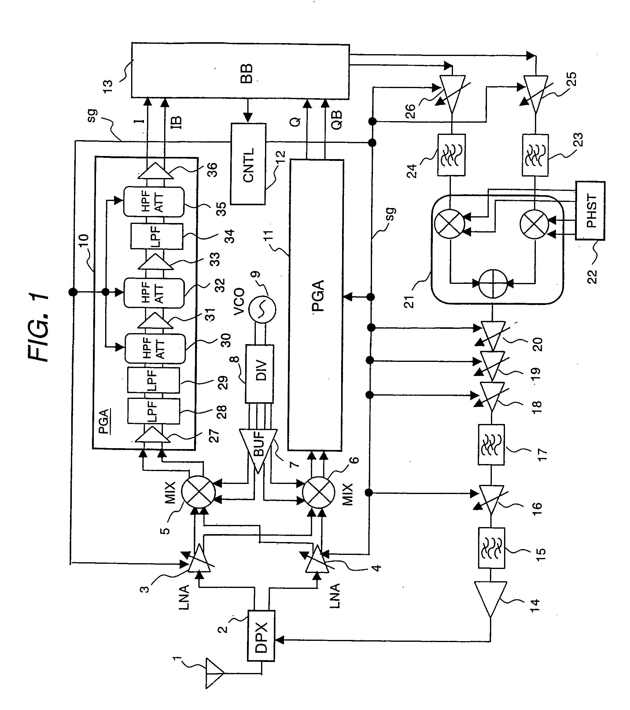
[0025]FIG. 1 is a circuit block diagram of a direct-conversion transmitter / receiver showing a first embodiment of the present invention. In FIG. 1, components shared between transmitting and receiving functions are antenna 1 for transmitting and receiving signal, duplexer (DPX) 2 suppressing leakage of a received signal into the transmitting system and suppressing leakage of a transmitted signal into the receiving system, base-band block (BB) 13 for performing analog-digital conversion and digital-analog conversion of a received signal for outputting the signal, and controller (CNTL) 12 receiving signals from base-band block 13 for outputting control signal sg to each circuit.

[0026] The receiving system is made up of low noise amplifiers (LNA) 3 and 4 formed of a differential amplifier for amplifying a high-frequency signal received through antenna 1, mixers (MIX) 5 and 6 for frequency converting a received signal, voltage-controlled oscillator (VCO) 9 for generating a local signal...


PUM


Abstract

To reduce circuit area and power consumption and suppress transient response occurring at switching in PGA of a programmable gain amplifier is provided a wireless communication receiver comprising PGAs for adjusting the gain of a received signal down-converted by mixers and sending it to base-band block. Within PGAs are provided HPFATT circuits formed of capacitors arranged in series, and ladder resistors arranged in parallel, with signal lines, and a plurality of switches. HPFATT is a circuit serving as a high-pass filter and an attenuator for gain switching, wherein switches are controlled by control signal sg from a controller. Amplifiers connected to the rear stage of the HPFATT circuit are formed of MOS transistors.

Description

CROSS-REFERENCE TO RELATED APPLICATION [0001] The present application claims priority from UK patent application No. GB 0414682.5 filed on Jun. 30, 2004, the content of which is hereby Incorporated by reference into this application. BACKGROUND OF THE INVENTION [0002] The present invention relates to a wireless communication receiver and, more particularly, it relates to a wireless communication receiver capable of setting up a gain attenuation by switching over a plurality of switches in a programmable gain amplifier. [0003] In a conventional wireless communication receiver in which signal lines are AC-coupled, a transient response occurs when the gain of programmable gain amplifier composed of a multiple stages of amplifiers is switched. As measures to cope with the transient response, there is known such a method as to perform the switching of gain at timing except when a control signal or a signal susceptible to noises is received (refer to, for example, Japanese Patent Laid-ope...

Claims


Application Information

Patent Timeline
IPC IPC(8): H04B1/06H04B7/00H03G1/00H03G3/30H04B1/707H04J13/00
CPCH03G1/0088H03G3/3052Y02B60/50
Inventor IKUTA, ISAOYAMAMOTO, AKIOIGARASHI, YUTAKAGOODWIN, STEPHEN
Owner RENESAS TECH CORP
Why Eureka
Eureka Blog
Learn More