
Low impact spot welding cylinder using single piston

Active Publication Date: 2006-06-15
DOBEN LTD
View PDF16 Cites 7 Cited by
  • Summary
  • Abstract
  • Description
  • Claims
  • Application Information

AI Technical Summary

Benefits of technology

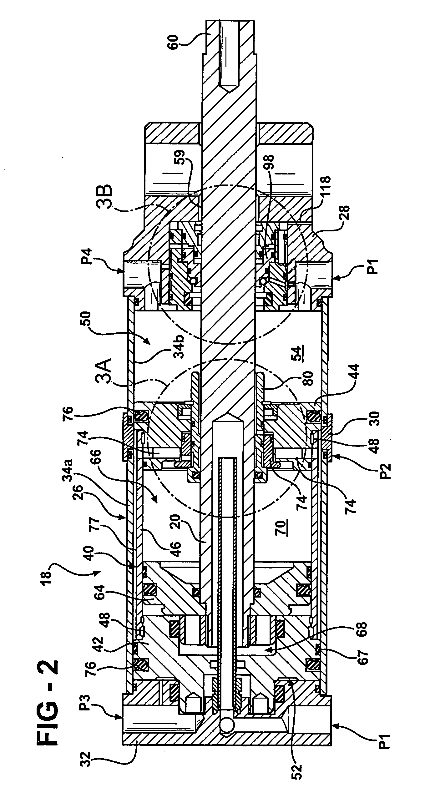
[0008] The present provides a weld cylinder having a single or dual piston arrangement. The cylinder has a movable retract piston assembly with the piston arranged within the retract piston assembly. The piston supports a rod that is movable between home, intermediate, work, and fully advanced work positions. The rod moves rapidly from the home position to the intermediate position. However, the rod moves more slowly from the intermediate position to the work position to reduce the impact force. A cushion valve supported by the retract piston assembly and a cushion trip valve supported by a front block cooperate to increase the rate at which the rod moves from the work position to the advanced position so that weld force increases rapidly to minimize increases in cycle time.
[0010] The cushion valve is a differential pressure valve that is exposed to the pressure within the cushion chamber and weld-forward air pressure. As the pressure in the cushion chamber falls as the chamber is exhausted and the weld-forward air pressure rises, the cushion valve will open. The opened cushion valve enables the cushion chamber to be exhausted even more rapidly so that the weld force can build quickly.
[0011] Accordingly, the present invention provides a pneumatic cylinder that reduces initial impact force between the welding caps and the workpiece, but that does not require additional, costly external devices and increases in cycle time.

Problems solved by technology

Repeated impact force between the welding caps and the workpiece plastically deforms the welding caps thereby increasing the wear of the welding caps and reducing the service life, which increases operating cost.
Impact force between the welding caps and workpiece also generates workpiece distortion, which can have detrimental effects on the welding process and quality of the weld.
However, while this approach reduces the impact force it also increases the cycle time for a spot weld, which is undesirable.
Another drawback is that typically the greater the retract stroke length, the narrower the low impact region becomes relative to the stroke.
This is problematic in that the internal components of the weld cylinder must be customized depending upon the application.
However, the addition of these externals devices may be difficult to integrate with existing weld guns and is also costly since additional components must be added to the welding system.

Method used


Image

  • Low impact spot welding cylinder using single piston
  • Low impact spot welding cylinder using single piston
  • Low impact spot welding cylinder using single piston

Examples


Embodiment Construction

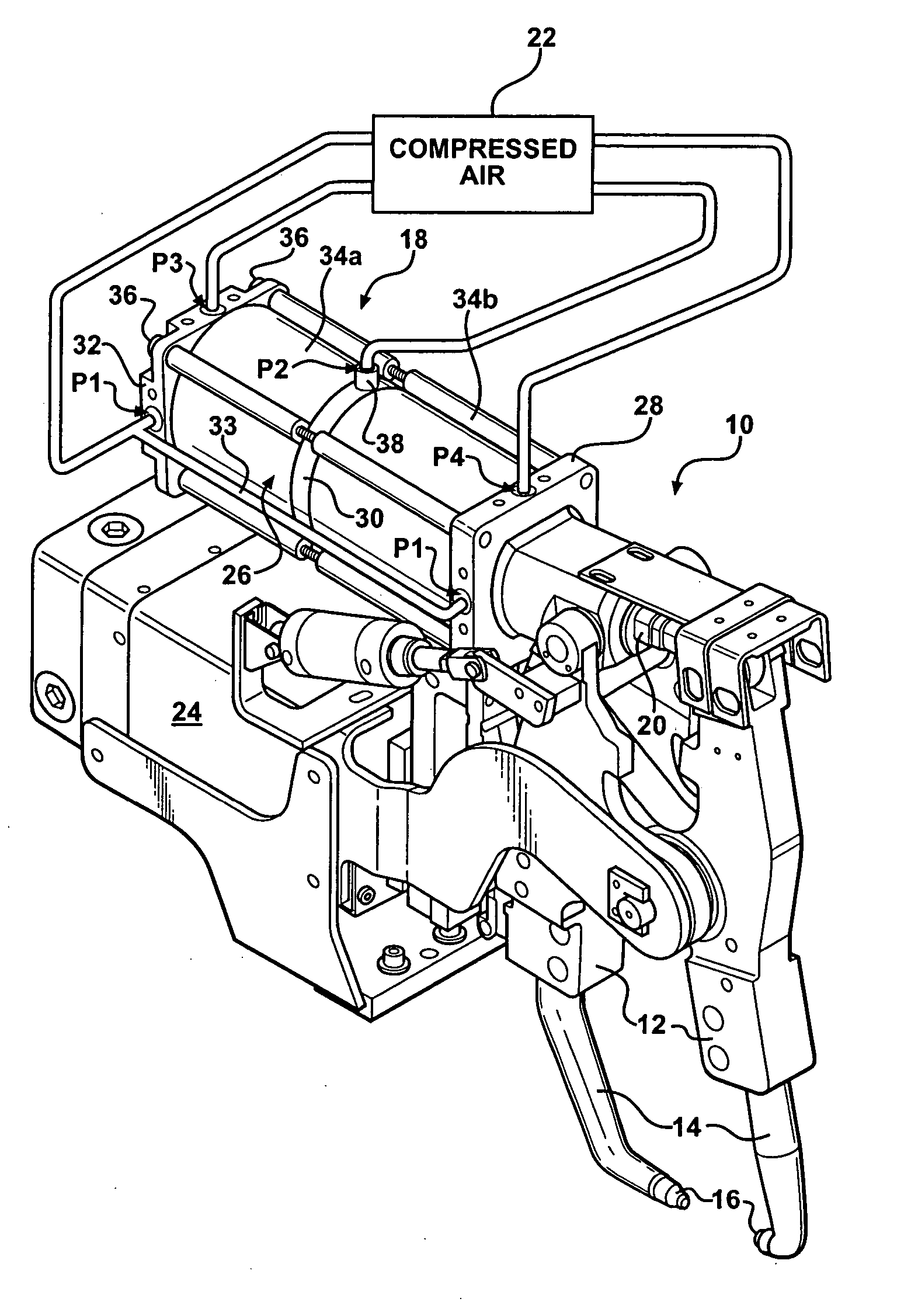
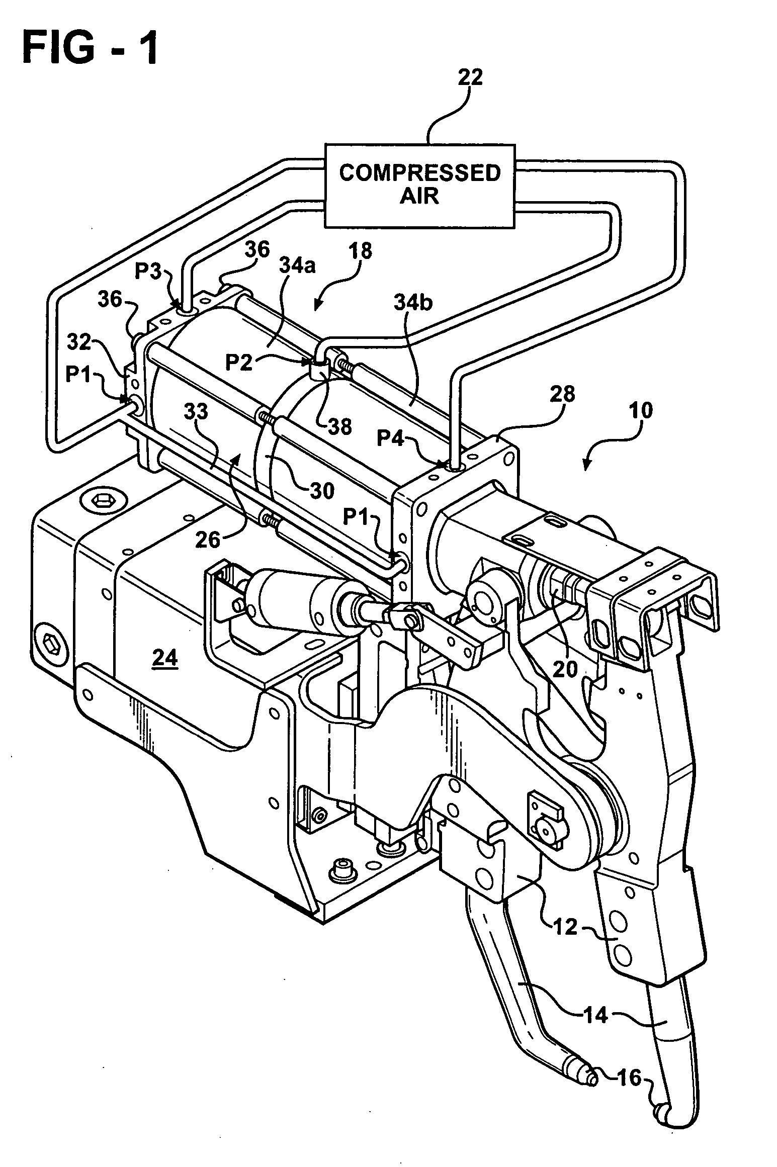
[0021] An inventive weld gun 10 including an inventive pneumatic cylinder 18 is shown in FIG. 1. The pneumatic cylinder 18 is a four port arrangement (P1-P4) that can be easily integrated into existing weld guns utilizing four ports. That is, the plumbing for prior art weld guns having four ports can be used with the inventive pneumatic cylinder 18 without modification to the welding system. The ports P1-P4 are fluidly connected to a compressed air source 22. A fluid line 33 interconnects two ports P1 on the pneumatic cylinder 18. The ports P1-P4 are connected to the compressed air source 22 though valves that control the timing of the air signals provided to the pneumatic cylinder 18 by selectively opening and closing the valves.

[0022] The weld gun 10 includes opposing arms 12 that each include an electrode 14. The electrodes 14 include welding caps 16 that are typically manufactured from a malleable copper alloy. The welding caps 16 engage a workpiece (not shown) to apply a weldi...


PUM

PropertyMeasurementUnit
Pressureaaaaaaaaaa

Abstract

A weld cylinder having a single piston arrangement is provided. The cylinder has a movable retract piston assembly with the piston arranged within the retract piston assembly. The piston supports a rod that is movable between home, intermediate, work, and advanced work positions. The rod moves rapidly from the home position to the intermediate position however, the rod moves more slowly from the intermediate position to the work position to reduce the impact force. A cushion chamber slowly exhausts through a hole in the cushion valve while an isolator is in an open position. Once the cushion valve opens in response to a weld-forward pressure on the cushion valve, the cushion chamber exhausts rapidly so that weld force increases rapidly to minimize increases in cycle time.

Description

[0001] The application claims priority to U.S. Provisional Application No. 60 / 635,086 filed Dec. 10, 2004.BACKGROUND OF THE INVENTION [0002] The present invention relates to a weld gun used in spot welding, and more particularly, the invention relates to either a single or double piston welding cylinder for the weld gun generating a low impact force when the weld gun engages the workpiece to perform a spot weld. [0003] A typical weld gun used in spot welding includes opposing arms each having an electrode that applies current to a workpiece to generate a weld nugget, for example, between two sheets of metal. The electrodes include malleable welding caps typically manufactured from a copper alloy. Repeated impact force between the welding caps and the workpiece plastically deforms the welding caps thereby increasing the wear of the welding caps and reducing the service life, which increases operating cost. [0004] Impact force between the welding caps and workpiece also generates work...

Claims


Application Information

Patent Timeline
IPC IPC(8): B23K11/10
CPCB23K11/314B23K11/315F15B11/036F15B11/0365F15B11/121F15B15/1409F15B15/22F15B15/225F15B2211/50563F15B2211/5154F15B2211/7055F15B2211/76
Inventor TENZER, PETER
Owner DOBEN LTD
Learn More