
Controlled auto-ignition two-stroke engine

a two-stroke engine and ignition technology, applied in the direction of mechanical equipment, lift valves, output power, etc., can solve the problems of limiting the instantaneous flow to the cylinder, reducing the pressure, etc., and achieve the effect of limiting the instantaneous flow and improving the pressure balan

Inactive Publication Date: 2006-06-15
FABREGA JUANA ELISABETH
View PDF16 Cites 13 Cited by
  • Summary
  • Abstract
  • Description
  • Claims
  • Application Information

AI Technical Summary

Benefits of technology

[0004] The method to operate the described engine consists of the following phases: during the piston downward movement in the expansion stroke, the exhaust port is opened by the piston setting the exhaust advance, the rotary valve adjacent to the exhaust port enables the release of the exhaust gases, and therefore they flow to the exhaust system. As the piston continues its downward movement it opens the intake ports, so the reeds of the reed valves housed in the transfer ports begin to get opened by the pressure created in the crankcase thus allowing the passage of the air-fuel mixture but producing a drecrease of pressure and limiting the instantaneous flow to the cylinder. As a consequence, the thermo chemical activation of part of the fuel contained in the air-fuel mixture is improved since there is a better pressure balance between the exhaust residual gases and the air-fuel mixture.
[0006] In this way, very low fuel consumption and emission levels can be achieved, whether hydrocarbons, carbon monoxide or NOx.

Problems solved by technology

As the piston continues its downward movement it opens the intake ports, so the reeds of the reed valves housed in the transfer ports begin to get opened by the pressure created in the crankcase thus allowing the passage of the air-fuel mixture but producing a drecrease of pressure and limiting the instantaneous flow to the cylinder.

Method used


Image

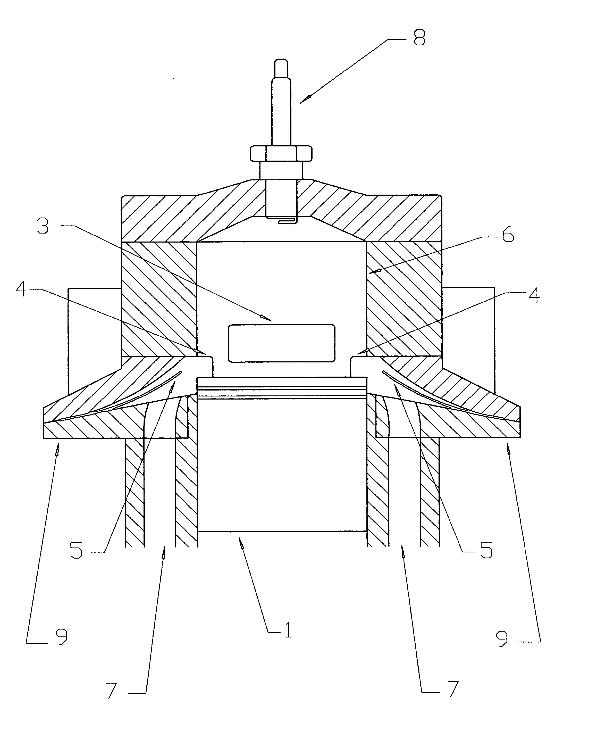
  • Controlled auto-ignition two-stroke engine
  • Controlled auto-ignition two-stroke engine
  • Controlled auto-ignition two-stroke engine

Examples


Embodiment Construction

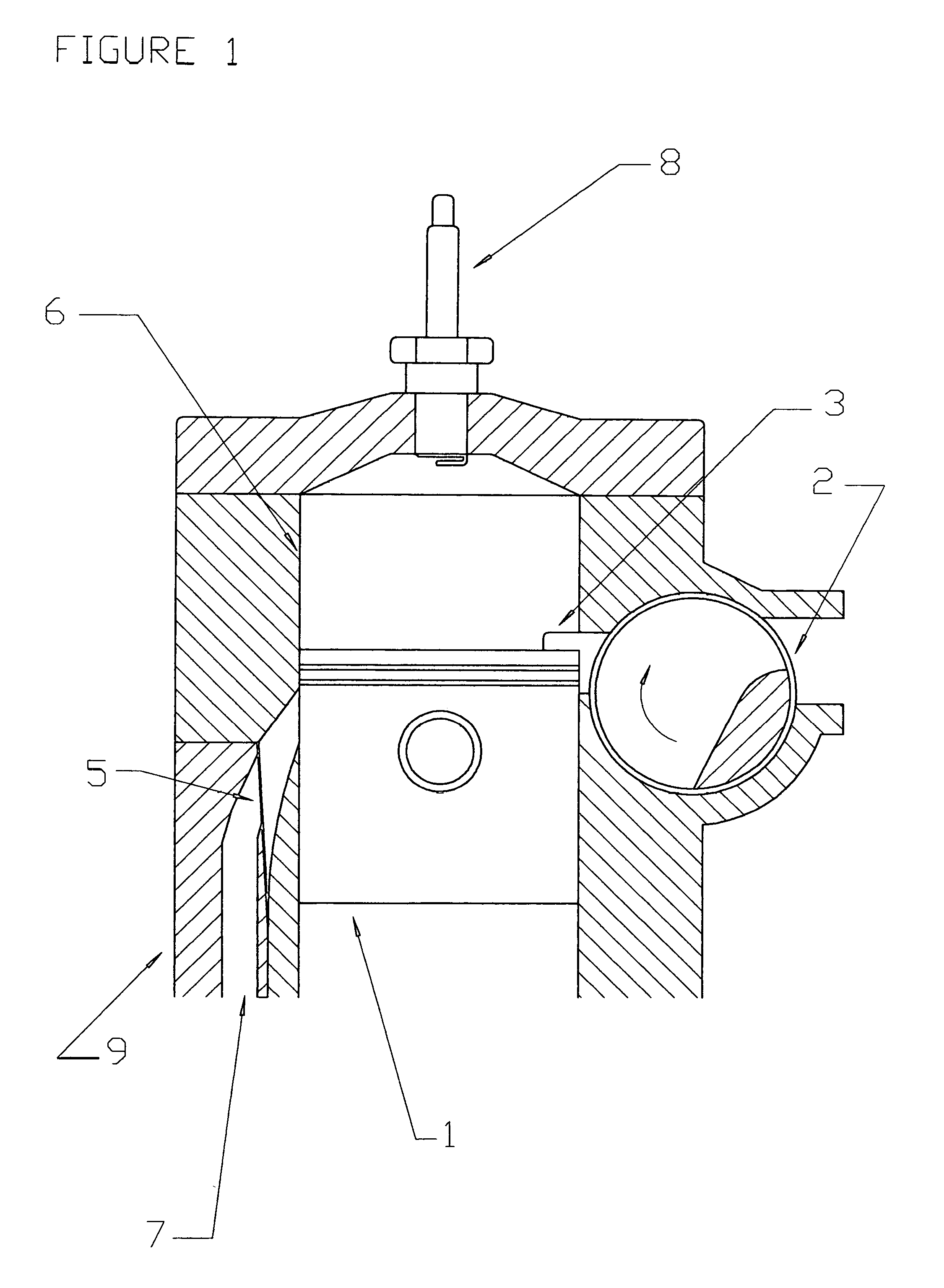
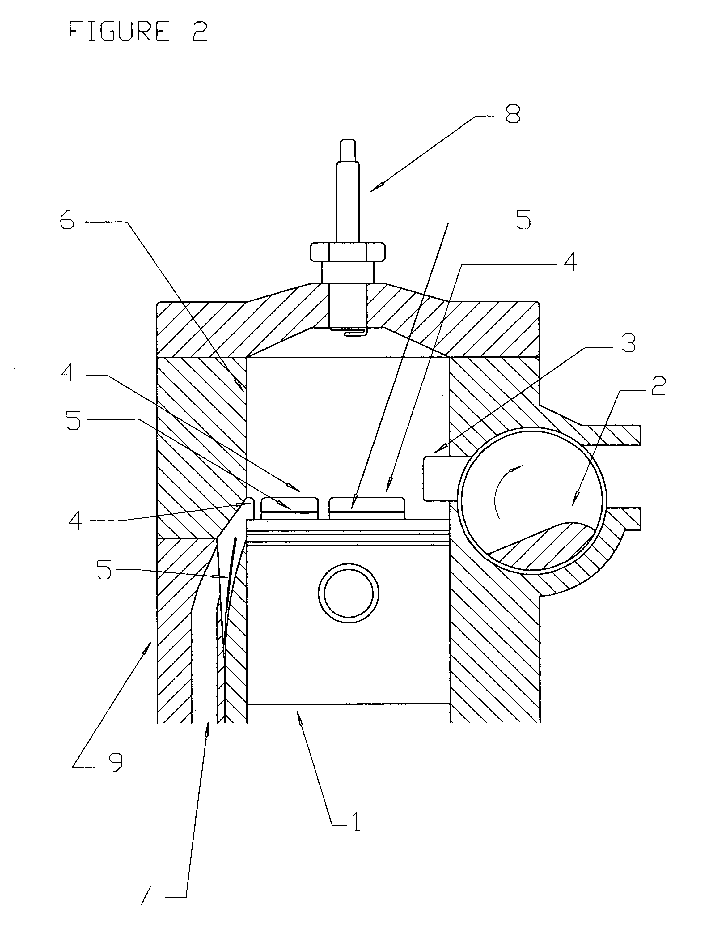
[0020] To exemplify the invention, it will be used an alternate single cylinder (6) controlled auto-ignition or spark ignition two-stroke engine with crankcase scavenging, low compression ratio, fed by a carburetor with homogeneous air-fuel mixture. Said engine has a reed valve between the carburetor and the crankcase, a rotary valve (2) adjacent to the cylinder (6) exhaust port (3) which rotates in the same direction that the crankshaft (clockwise) at a 1 to 1 transmission ratio and also has reed valves (9) in the transfer ports (7).

[0021] During the downward movement of the piston (1) in the expansion stroke, it opens the exhaust port (3) setting the exhaust advance and starting the release of the exhaust gases to the exhaust system since the rotary valve (2) enables the passage of the exhaust gases, as shown in FIG. 1.

[0022] Going on with its downward movement, the piston (1) opens the intake ports (4), as shown in FIGS. 2 and 3, due to the pressure generated in the crankcase b...


PUM


Abstract

A controlled auto-ignition or spark ignition two stroke piston engine, fed by homogeneous air-fuel mixture, with crankcase scavenging, in which the amount of air-fuel mixture transferred from the crankcase to the cylinder is not greater than the 50% of the cylinder volume; said engine has reed valves in the transfer ports that connect the crankcase to the cylinder to control the internal dynamics of the air-fuel mixture, limiting the instantaneous maximum flow that is transferred to the cylinder in order to achieve the best stratification level among the air-fuel mixture and the exhaust residual gases, getting this way the thermo chemical activation of part of the fuel contained in the mixture. Said engine also has a rotary valve adjacent to the cylinder exhaust port that rotates in synchronism with the crankshaft, which closes the exhaust port a few degrees after the piston reaches the bottom dead center, thus preventing the leakage of the thermo chemically activated mixture and holding part of the burnt gases inside the cylinder. Then, during the compression stroke, more heat is given to the thermo chemically activated mixture decomposing part of the fuel contained in it into activated radicals which act as igniters when close to the top dead center firing the mixture in a simultaneous and complete way, thus obtaining very low levels of CO, HC and Nox emissions, as well as low fuel and oil consumption.

Description

TECHNICAL FIELD OF THE INVENTION [0001] It applies to spark ignition two-stroke piston engines having crankcase scavenging and exhaust port / s, and which are fed with air-fuel mixture by carburetors or fuel injectors. BACKGROUND OF THE INVENTION [0002] Spark ignited two stroke engines with crankcase scavenging and fed by air-fuel mixture are light weight, simple and inexpensive both to manufacture and to maintain for the user, but have the disadvantages of great fuel consumption and high emissions. When idling, these engines have problems to concentrate the air-fuel mixture near the spark plug thus producing misfiring and consequently getting an unstable combustion. Besides, both idling and at other revolutions and charge conditions, part of the air-fuel mixture is sent from the cylinder to the exhaust system demanding great fuel consumption and producing high levels of hydrocarbon emissions. BRIEF DESCRIPTION OF THE INVENTION [0003] The present invention is related to a controlled a...

Claims


Application Information

Patent Timeline
IPC IPC(8): F02B33/04F02B25/00F02D13/02
CPCF01N1/08F02B25/04F02B25/24F02B33/04F02D9/16F02D9/18F02D2009/0216
Inventor FABREGA, JUANA ELISABETH
Owner FABREGA JUANA ELISABETH
Learn More