
Carbon-nanotube cold cathode and method for fabricating the same

a carbon-nanotube and cold cathode technology, applied in the manufacture of discharge tubes/lamps, electrode systems, discharge tube main electrodes, etc., can solve the problems of poor electron emission efficiency, reducing the lifetime of fed, and restricting the dimensions of fed correspondingly, and achieve high electron emission efficiency

Inactive Publication Date: 2006-05-18
CHUNGHWA PICTURE TUBES LTD
View PDF1 Cites 16 Cited by
  • Summary
  • Abstract
  • Description
  • Claims
  • Application Information

AI Technical Summary

Benefits of technology

[0009] In view of the foregoing, this invention provides a carbon-nanotube cold cathode and a method for fabricating the same, which can implant carbon nanotubes to a cathode substrate substantially vertical to the surface thereof under low temperature. Therefore, the cold cathode can have high electron emission efficiency.
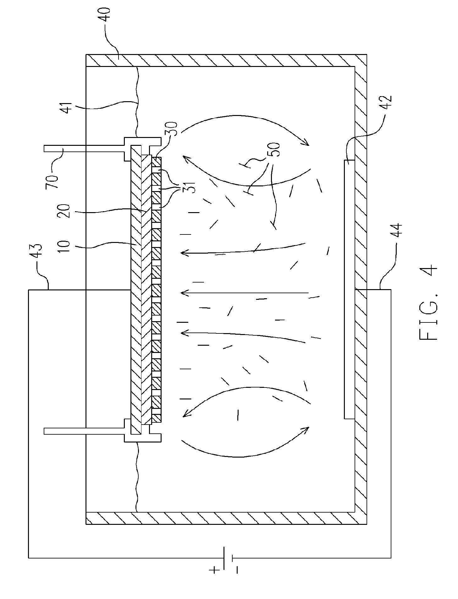
[0012] Since the anodized metal film having nanopores therein can serve as a template for the carbon nanotubes in the electrodeposition step, the carbon nanotubes can be orientated substantially vertical to the surface of the cathode substrate to improve electron emission efficiency. Moreover, the through nanopores in the metal film are formed uniformly, so that the carbon nanotubes are distributed uniformly on the substrate. Furthermore, since the carbon nanotubes are deposited substantially vertical to the surface of the cathode substrate, the density of carbon nanotube on the cold cathode can be increased to further increase the emission current density. In addition, the temperature for electrodeposition is so low that a glass cathode substrate can be used.

Problems solved by technology

However, since the lithography method and the evaporation deposition are limited in the substrate size, the dimensions of FED are restricted correspondingly.
Moreover, the tip of such an emitter is degraded rapidly, decreasing the lifetime of FED.
However, the carbon nanotubes applied to the cathode substrate with such methods are mostly parallel to the substrate surface, so that the electron emission efficiency is poor.
Moreover, the screen-printing process in the method of U.S. Pat. No. 6,359,383 requires a large amount of carbon nanotubes, and the coating slurry and the screen used in the screen-printing process are easily contaminated.
Meanwhile, the carbon nanotubes formed with CVD have poor electron emission efficiency.

Method used


Image

  • Carbon-nanotube cold cathode and method for fabricating the same
  • Carbon-nanotube cold cathode and method for fabricating the same
  • Carbon-nanotube cold cathode and method for fabricating the same

Examples


Embodiment Construction

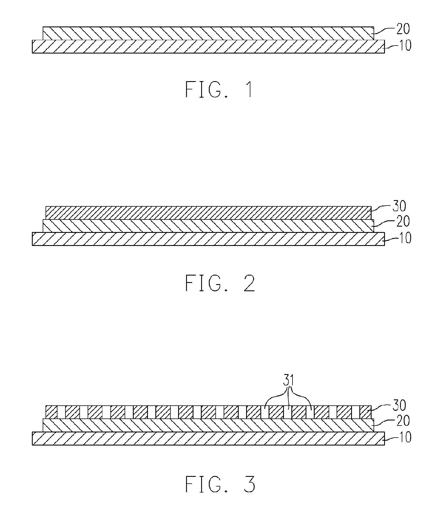
[0015] Referring to FIG. 1, a plate-like cathode substrate 10 is provided, which is a glass substrate, a silicon-based substrate or an aluminum oxide substrate, for example. A conductive layer 20 is then deposited on the cathode substrate 10 through evaporation deposition or sputtering deposition. The material of the conductive layer 20 is, for example, TiN or Ti.

[0016] Referring to FIG. 2, a metal film 30 is selectively formed on the conductive layer 20 through, for example, evaporation deposition or sputtering deposition. The thickness of the metal film 30 is smaller than the length of the carbon nanotubes that will be deposited latter, and the material of the metal film 30 may be aluminum, for example.

[0017] Referring to FIG. 3, an anodization treatment is done to the metal film 30 to form numerous nanopores 31 through the metal film 30. The nanopores 31 are formed uniformly and have a diameter from about 5 nm to 500 nm. The distribution density and the diameter of the nanopore...


PUM

PropertyMeasurementUnit
diameteraaaaaaaaaa
weight ratioaaaaaaaaaa
voltageaaaaaaaaaa

Abstract

A method for fabricating a carbon-nanotube cold cathode is described. A conductive layer is formed on a substrate, and then a metal film is selectively formed on predetermined emitter regions of the conductive layer. An anodization treatment is done to the metal film to form numerous nanopores through the metal film. Thereafter, carbon nanotubes are deposited into the nanopores through electrodeposition, wherein one end of each carbon nanotube is exposed outside a corresponding nanopore of the metal film.

Description

BACKGROUND OF THE INVENTION [0001] 1. Field of the Invention [0002] The present invention relates to an electronic element and a method for fabricating the same. More particularly, the present invention relates to a carbon-nanotube cold cathode and a method for fabricating the same with electrodeposition. [0003] 2. Description of Related Art [0004] Recently, various types of flat panel display (FDP) are developed to replace traditional CRT displays, featuring much less weight and thickness, low energy consumption and reduction / elimination of harmful electromagnetic radiation. Today, the most popular type of FDP is surely the liquid crystal display (LCD). However, other types of FPD, including plasma display, projection-type display, organic electroluminescent (OEL) display and field emission display (FED), are also attracting much attention. It is expected that these types of FDP would be superior in cost reduction and performance, especially in energy saving, resolution, response t...

Claims


Application Information

Patent Timeline
Patent Type & Authority Applications(United States)
IPC IPC(8): H01J1/02H01J1/14H01J9/04
CPCB82Y10/00H01J1/3042H01J9/025
Inventor TSUEI, LI-REN
Owner CHUNGHWA PICTURE TUBES LTD
Learn More