
Gas cleaning process and equipment therefor

a technology of gas cleaning and equipment, applied in auxillary pretreatment, mixing machines, using liquid separation agents, etc., can solve the problems of inability to achieve removal efficiencies of above 90% of particle sizes relative large bulk of the known wet scrubbing system, and inability to achieve the removal efficiency of over 90% of particle sizes of less than 0.05 micron, etc., to enhance the removal of vapour and enhance the effect of chemisorbtion

Inactive Publication Date: 2006-05-18
CLEAN GAS TECH
View PDF10 Cites 11 Cited by
  • Summary
  • Abstract
  • Description
  • Claims
  • Application Information

AI Technical Summary

Benefits of technology

[0024] It is accordingly a first object of the present invention to provide a relatively inexpensive, but effective method for the removal of relatively fine particulates from a gas stream, using a scrubbing fluid, and the subsequent separation of the gas and the scrubbing fluid, such as that required for the scrubbing of the hot off-gases from the Sinter and other furnace related processes.
[0025] It is a second object of the present invention to provide relatively inexpensive, but effective, equipment for use in the removal of the particulates from the gas stream, and the subsequent separation of the gas and the scrubbing fluid.

Problems solved by technology

In many instances, however, the proportion of alkali salts (potassium and sodium salts) causes the dust that is to be removed, unsuitable for bag filters and normal electrostatic precipitators, leaving wet electrostatic precipitators as the only existing technology option which is capable of meeting the current requirements regarding final dust concentrations.
A disadvantage of these wet scrubbing processes and systems is however their inability to achieve removal efficiencies of above 90% of particle sizes of less than 0.05 micron.
A further disadvantage is the relative large bulk of the known wet scrubbing systems.
Another disadvantage of the known wet scrubbing systems is the relatively large floor area required by those systems that are capable of achieving removal efficiencies of above 90% of particle sizes of less than 0.05 micron, such as the conventional Electrostatic Precipitator (“ESP”) or the bag house installation.
An additional disadvantage of the typical primary equipment, or components of the assemblies, or so-called packs of components used in the known wet scrubbing systems is the relative difficulty with which they are moulded or cast, using low cost plastics, resins and reinforced plastics or resins (with or without abrasion inhibiting fillers).
A further disadvantage of the equipment and components is the relative difficulty with which they are assembled and maintained, typically requiring the use of specialist tools and / or support services.
This reduced velocity and the orientation of this velocity with regard to the subsequent flow profile, results in specific disadvantages, including a relatively smaller number of larger droplets, thereby presenting a substantially reduced droplet surface area; and lack of penetration in that the majority of the droplets do not penetrate relatively far into the gas flow before the following bend causes them to move back towards the wall again as a result of both centrifugal action and inertia.
The resultant substantially reduced droplet surface area causes a relatively poor scrubbing efficiency per unit volume of scrubbing fluid that is released from the surface of the flow profile.
An additional disadvantage of partial contact of the gas with the scrubbing fluid, is that each time the scrubbing fluid leaves the solid surface of the walls of the flow profile, the gas flow tends to accelerate the droplets up to the gas velocity in that area, causing much of this additional velocity energy to be lost when the droplets re-combine with the film of fluid on the wall.
The energy loss per unit of dust or fine droplet removal, per unit of gas scrubbing, becomes particularly significant when the droplets do not contact much of the total gas flow.
A related disadvantage of the MSPR is therefore its inability to retain the relative velocities of the gas and fluid flow through the flow profile, allowing the decline in relative velocities to reduce the ability of the scrubbing fluid droplets to remove fine dust and other particulates.
A further disadvantage of the MSPR is the lack of overall wear and chemical resistance of the material used for the manufacture of the MSPR as well as its ability to with stand environments of high impact, abrasion, corrosion and temperature demands such as those present with the scrubbing of the hot off-gases from the Sinter and other furnace related processes.

Method used


Image

  • Gas cleaning process and equipment therefor
  • Gas cleaning process and equipment therefor
  • Gas cleaning process and equipment therefor

Examples


Embodiment Construction

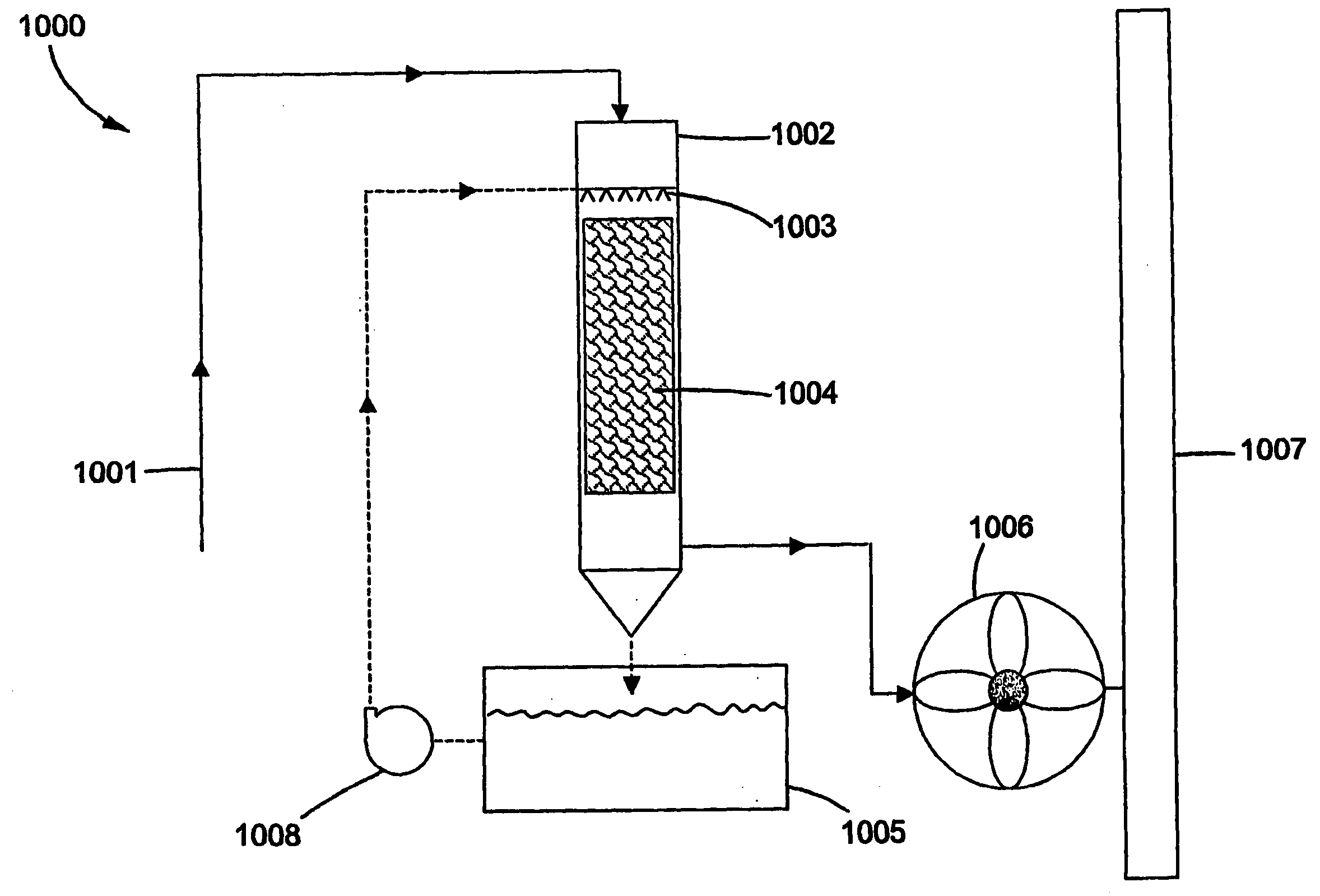
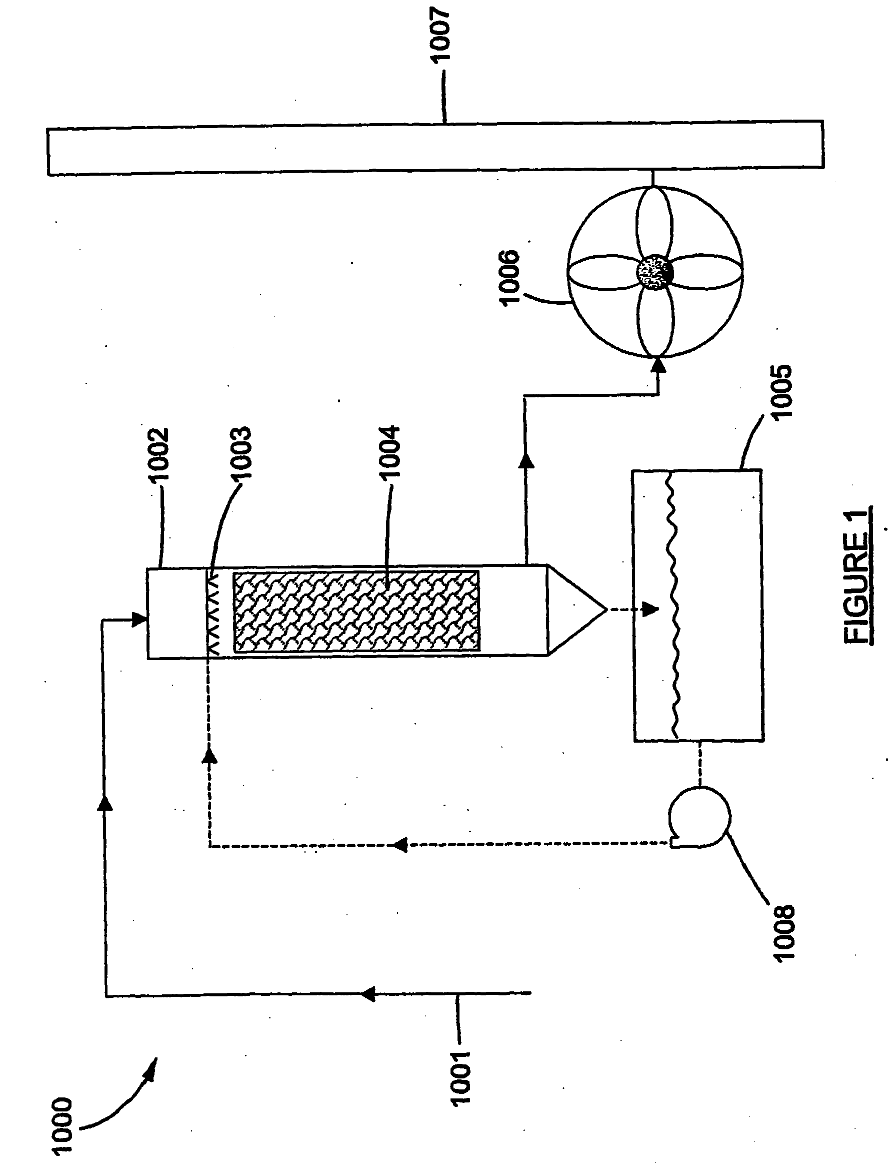
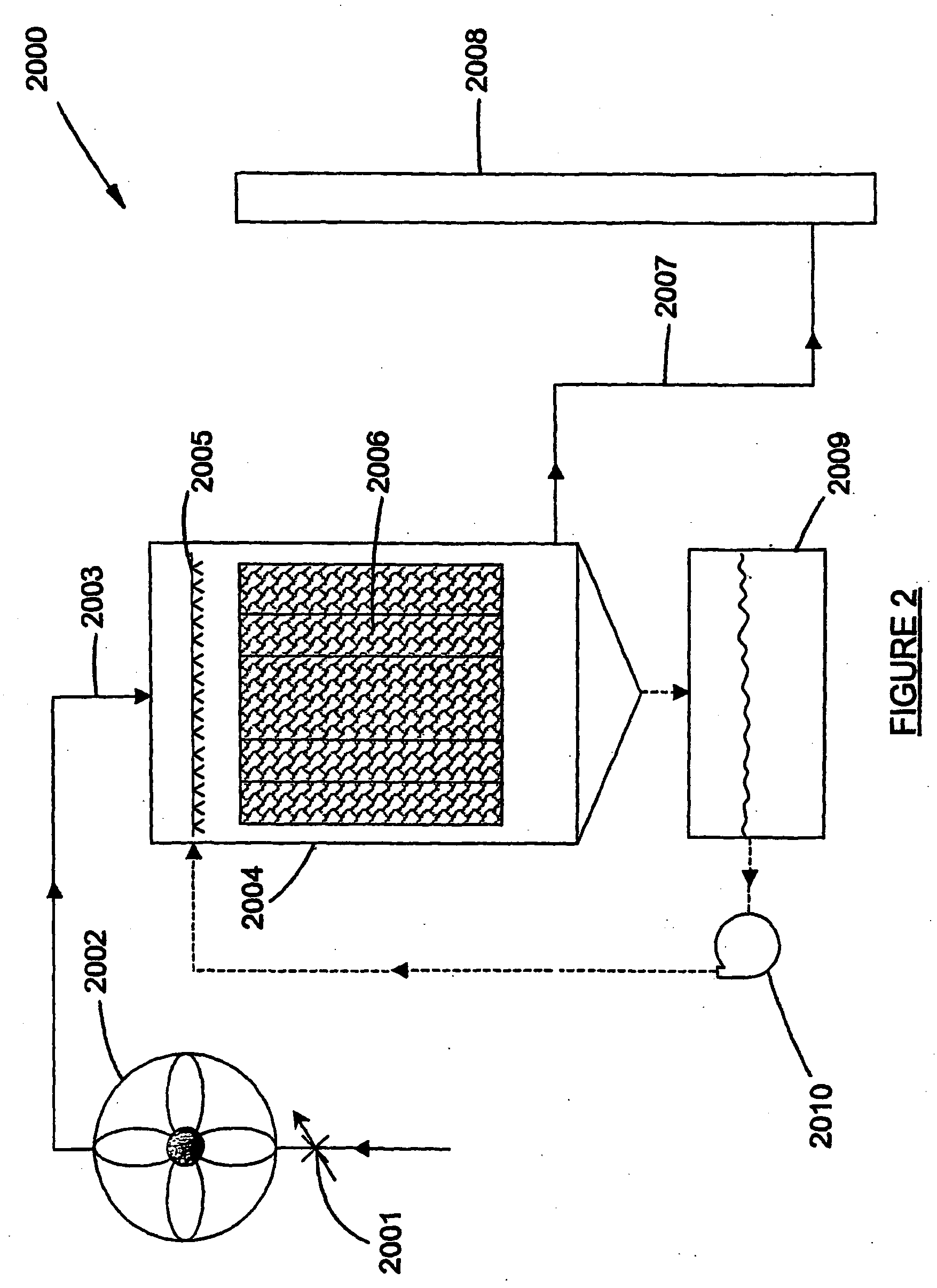
[0058] A preferred embodiment of the invention win now be described by means of a non-limiting example only and with reference to the various aspects of the invention and the accompanying drawings.

[0059] A single high intensity mixing and contacting device or so-called MSPR, was modified in accordance with the invention. The modified MSPR was used in pilot plants designed for the removal of relatively fine particulates from a gas stream, using a scrubbing fluid, and the subsequent separation of the gas and the scrubbing fluid, the gas stream being part of the hot off-gases from the Sinter and other furnace related processes at one of the Iscor Limited iron making facilities at Vanderbilt Park, South Africa.

[0060] The hot off-gases from the Sinter and other furnace related processes, so-called sinter gas, was generated during the sintering of a mixture of fine ores, additives, iron-bearing recycled materials from downstream operations such as coarse dust and sludge from blast-furna...


PUM

PropertyMeasurementUnit
Temperatureaaaaaaaaaa

Abstract

The invention relates to equipment for use in the removal of relatively fine particulates from a first substance, using a second substance. The equipment includes a static, co-current contacting mixer section, having a plurality of stages defining a flow path, with a flow profile, for the first and the second substance, at least some of the stages being shaped to define a substantially curved flow path having an effective centre of curvature located to one side of the flow path, and wherein each adjacent stage has a centre of curvature on an opposite side of the flow path to provide a point of inflexion between adjacent stages and whereby, as the substances flow through the reactor between the adjacent stages, particles present in the first substance migrate through the second substance, first in one direction and then in a substantially opposite direction to promote interphasic interaction between the first and the second substance, the flow path characterised in being provided with an edge formation between at least two adjacent stages towards the point of inflexion so as to enhance the launch of the second substance on the outside of the curved flow path of one stage at relatively high velocity from the edge formation to the inside of the curved flow path of the adjacent stage, thus increasing the contact between the first and the second substances. The equipment also includes a cyclonic section and a spinner section. The invention also relates to a method for the removal of relatively fine particulates from a gas stream, using a scrubbing fluid, as well as a plastic composite material for the manufacture of the equipment.

Description

TECHNICAL FIELD [0001] This invention relates to a gas cleaning process and equipment therefor. [0002] More particularly but not exclusively, the invention relates to the removal of relatively fine particulates from a gas stream, using a scrubbing fluid, and the subsequent separation of the gas and the scrubbing fluid, as well as equipment therefor. [0003] This invention further relates to plastic and abrasion resistant composite materials for the manufacture of the equipment for the removal of the particulates from the gas stream and the subsequent separation of the gas and the scrubbing fluid. BACKGROUND ART [0004] The removal of relatively fine particulates from a gas stream, using a scrubbing fluid, together with the subsequent separation of the gas and the scrubbing fluid, is well known, and is often carried out by means of a so-called wet scrubbing process. [0005] More particularly, the removal of relatively fine particulates from a gas stream, using a scrubbing fluid, and the...

Claims


Application Information

Patent Timeline
IPC IPC(8): B01D53/02B01D47/00B01D51/02B01F5/06B01J19/24C08K3/14C22B1/16C22B7/02
CPCB01D47/00B01D51/02C22B1/16C22B7/02Y02P10/20
Inventor PAXTON, RICHARD GEORGEFELLOWS-SMITH, MICHAELMINSZENTY, FRIEDRICH MICHAELMINSZENTY, CHRISTIAN ALEXANDER
Owner CLEAN GAS TECH
Learn More