
Method and apparatus for providing a rammed aggregate pier

a technology of aggregate piers and rammed piers, which is applied in the field of civil and construction engineering, can solve the problems of reducing the possibility of subsequent loss of structural integrity of cavities, and achieve the effect of reducing the propensity for bulging

Active Publication Date: 2006-04-27
GEOPIER FOUND
View PDF12 Cites 45 Cited by
  • Summary
  • Abstract
  • Description
  • Claims
  • Application Information

AI Technical Summary

Benefits of technology

[0021] Another object of the present invention is the provision of new and improved methods for radially compacting the side wall of a cavity as it is being formed so as to reduce the possibility of side wall deterioration during subsequent construction procedures.
[0023] Another object is to provide an improvement in the strength and stiffness of the piers by producing improved methods for aggregate compaction during construction of the pier shaft and the top of the pier.
[0026] It is a further object of the invention to provide a method and apparatus for mechanical densification of the soil and formation of stiffened piers that is more efficient than prior techniques and which may be used in a wider range of soils.
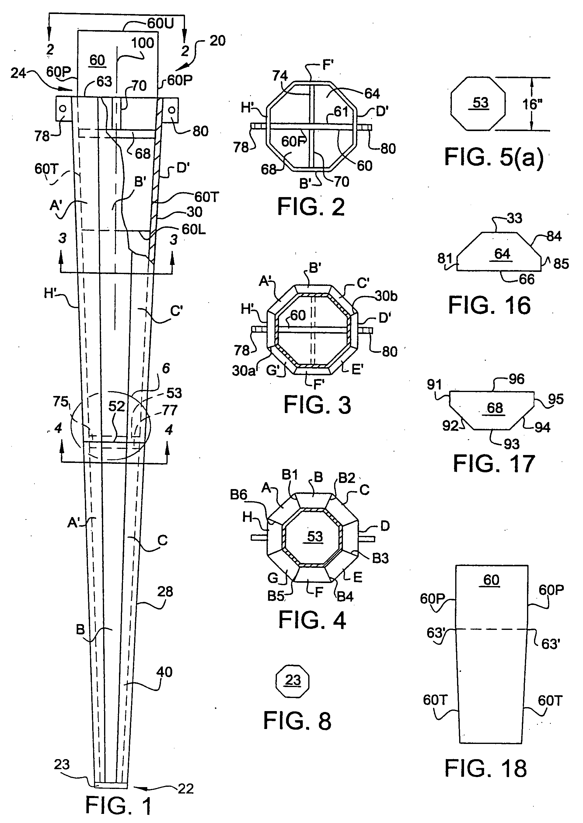
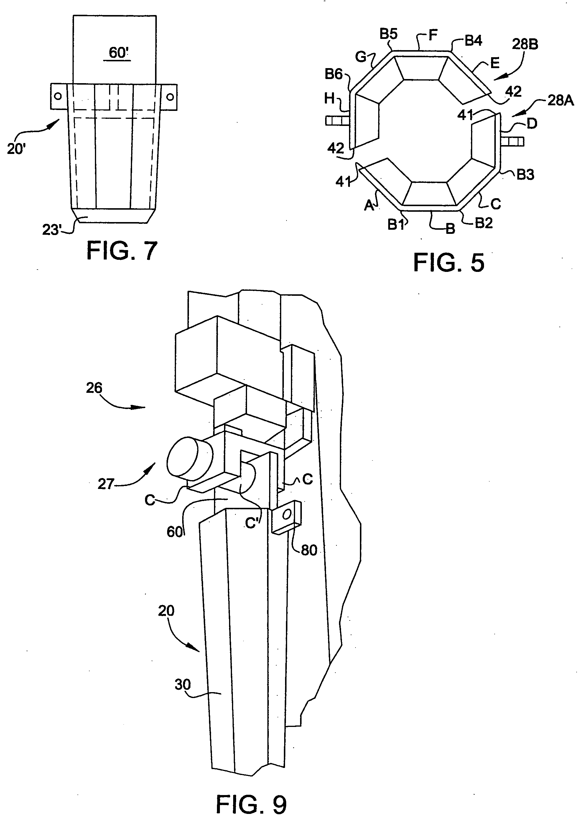
[0030] The unique primary mandrel has a hollow shell-frame preferably formed of steel plate having an octagonal cross-section. However, other cross-sectional shapes could be used, including but not limited to square, hexagonal and circular. The shell-frame is preferably formed of an upper half-shell component and a lower half-shell component which are welded together at the mid-point of the primary mandrel to provide a rugged and effective structure at reduced cost.
[0032] Achievement of the foregoing objects of the present invention is enabled by a unique primary mandrel for forming cavities in the earth which tapers inwardly from its upper end to a blunt lower end with the distance between the upper end and the lower end being at least equal to the height of the aggregate pier to be formed in a cavity formed by the primary mandrel. Typically, the taper or pitch angle of the primary mandrel relative to the axis of the mandrel is constant and will fall in the range of about 1.0 to about 5.0 degrees so that vertical movement of the mandrel which is effected by both vertical static force and vertical vibratory force creates essentially lateral radial forces on the surrounding earth. These lateral radial forces serve to compact and stabilize the entire sidewall surface of the cavity being formed and consequently greatly reduce the possibility of subsequent loss of structural integrity of the cavity during the extraction of the mandrel. The pitch angle of the primary mandrel is selected for different soil profiles to achieve enhanced stability so that the mandrel may be lifted from the cavity without the need for temporary casing or drilling fluid to maintain sidewall stability. It is also consequently possible to avoid the need for temporary casing or drilling fluid to maintain sidewall stability during the deposit and compaction of aggregate deposited in the open cavity during subsequent pier building procedures.
[0037] The method additionally contemplates the use of telltales, uplift anchors and post grating to measure deflections, resist uplift-loads and reduce the propensity for bulging.

Problems solved by technology

These lateral radial forces serve to compact and stabilize the entire sidewall surface of the cavity being formed and consequently greatly reduce the possibility of subsequent loss of structural integrity of the cavity during the extraction of the mandrel.

Method used


Image

  • Method and apparatus for providing a rammed aggregate pier
  • Method and apparatus for providing a rammed aggregate pier
  • Method and apparatus for providing a rammed aggregate pier

Examples


Embodiment Construction

[0083] In describing preferred embodiments of the present invention as illustrated in the drawings, specific terminology is employed for the sake of clarity. However, the invention is not intended to be limited to the specific terminology so selected, and it is to be understood that each specific element includes all technical equivalents that operate in a similar manner to accomplish a similar purpose. It should also be understood that the directional and positional descriptions such as above, below, front, rear, upper, lower and the like are based upon the relative positions of the structural components illustrated in FIGS. 1, 2 and 3.

[0084] The present invention achieves the foregoing objects in a preferred embodiment by employment of a unique primary ground penetrating downwardly tapered mandrel, generally designated 20 (FIG. 1), which is typically about 10 to about 20 feet long and has a longitudinal axis 100. Primary mandrel 20 is often octagonal in cross-section and continuo...


PUM


Abstract

A primary earth penetrating mandrel formed of a hollow shell steel plate octagonal in cross-section has an upper end and a blunt lower end joined by an upwardly and outwardly tapered wall. The mandrel is driven downwardly in the earth to simultaneously form a vertical tapered cavity while compacting the sidewall of the cavity to provide structural integrity. The mandrel is then moved upwardly from the bottom of the cavity and aggregate is deposited in the bottom of the cavity following which the mandrel is lowered so that its blunt lower end engages the deposited aggregate and densifies the aggregate by vertical vibratory action and static force with these steps being repeated until the pier top is near the surface of the earth at which time the upper aggregate portions are densified by either the primary mandrel or a secondary mandrel having a substantially larger lower end surface than the lower end surface of the primary mandrel. A second embodiment includes a conduit in the primary mandrel for injecting concrete or grout into aggregate previously deposited in the cavity.

Description

CROSS-REFERENCE TO RELATED APPLICATIONS [0001] The present patent application is a utility application partially based on, and claims priority from, U.S. Provisional Application No. 60 / 622,363 filed on Oct. 27, 2004 and U.S. Provisional Application No. 60 / 623,350, filed on Oct. 29, 2004 by Nathaniel S. Fox, which are expressly incorporated herein in their entirety by reference.BACKGROUND OF THE INVENTION [0002] 1. Field of the Invention [0003] In a principal aspect, the present invention generally relates to a method of soil densification and improvement for purpose of forming a stiffened support pier in a cavity within the densified and improved soil. [0004] The present invention additionally relates generally to the field of civil and construction engineering and, more specifically, is directed to methods and apparatus for providing load supporting aggregate piers in the earth capable of supporting a multitude of possible structures including, but not limited to, buildings, roads,...

Claims


Application Information

Patent Timeline
IPC IPC(8): E02D5/30E02D7/00
CPCE02D3/08E02D5/46
Inventor WISSMANN, KORD J.MOXHAY, ALAN L.FOX, NATHANIEL S.
Owner GEOPIER FOUND
Learn More