Exposure device for immersion lithography and method for monitoring parameters of an exposure device for immersion lithography

an exposure device and immersion lithography technology, which is applied in the field of monitoring parameters of the exposure devices for immersion lithography, can solve the problems of temperature change in the resist layer, alteration of the refractive index of the immersion liquid, etc., and achieve the effect of simple and cost-effective determination

Inactive Publication Date: 2006-04-20
POLARIS INNOVATIONS
View PDF7 Cites 10 Cited by
  • Summary
  • Abstract
  • Description
  • Claims
  • Application Information

AI Technical Summary

Benefits of technology

[0016] In a further preferred embodiment, the step of providing the exposure device comprises the projection image field being defined by an exposure slit. The principle of a wafer scanner that is known in the art can also be applied to the method in accordance with this embodiment. The exposure slit leads to a smaller projection image field in comparison with a wafer stepper, with the result that the resolution capability is significantly increased.
[0018] In a further preferred embodiment, the semiconductor wafer is displaced at a speed of about 0.2 m / s. In order to increase the productivity of the photolithographic process, the speed at which the semiconductor wafer is displaced is chosen to be appropriately high without influencing the projection quality. Displacing the semiconductor wafer at a speed of about 0.2 m / s constitutes a customary value for present-day controllers and drives of the substrate holder, so that a cost-effective solution using conventional substrate holders can be achieved in the case of this embodiment of the method.
[0020] In a further preferred embodiment, the immersion liquid is emitted at a speed of about 0.7 m / s. The speed of the jet of immersion liquid from the nozzles is first of all important for homogeneous and bubble-free filling of the region of the projection image field. Secondly, this also achieves cooling of the resist layer which is heated by the light from the light source during the lithography.
[0023] In a further preferred embodiment, the step of providing the exposure device comprises the exposure device having a numerical aperture which is greater than 1. The crucial advantage of immersion lithography resides in a high value that can be obtained for the numerical aperture. A value which is greater than 1 cannot currently be achieved with conventional exposure technology. Together with the currently controllable k1 factor of 0.3 and the wavelength of 193 nm, it is thus possible to achieve a resolution capability of the exposure device of about 50 nm.
[0026] In a further preferred embodiment, the step of providing the analysis device comprises the analysis device being suitable to determine the electrical resistance of the immersion liquid as a further parameter of the immersion liquid during the successive projection. During the exposure operation, the reaction products in the resist layer as a result of the generally short-wavelength light from the light source also lead to an alteration of the electrical resistance of the immersion liquid, since the immersion liquid flushes reaction products out of the resist layer. By determining the electrical resistance of the immersion liquid, it is thus possible to estimate the degree of contamination.
[0029] In a further preferred embodiment, the step of providing the analysis device comprises the analysis device including a contact-less temperature measuring system with a laser diode. A temperature measuring system with a laser diode represents a simple and cost-effective possibility for determining the temperature. Since the temperature measurement is contact-less, the temperature measuring system can be integrated into the exposure device without relatively great difficulty.

Problems solved by technology

During the exposure operation, the reaction products in the resist layer as a result of the generally short-wavelength light from the light source also lead to an alteration of the refractive index of the immersion liquid.
Thus, during the exposure operation, the generally short-wavelength light from the light source leads to a temperature change in the resist layer.

Method used


Image

  • Exposure device for immersion lithography and method for monitoring parameters of an exposure device for immersion lithography
  • Exposure device for immersion lithography and method for monitoring parameters of an exposure device for immersion lithography
  • Exposure device for immersion lithography and method for monitoring parameters of an exposure device for immersion lithography

Examples


Embodiment Construction

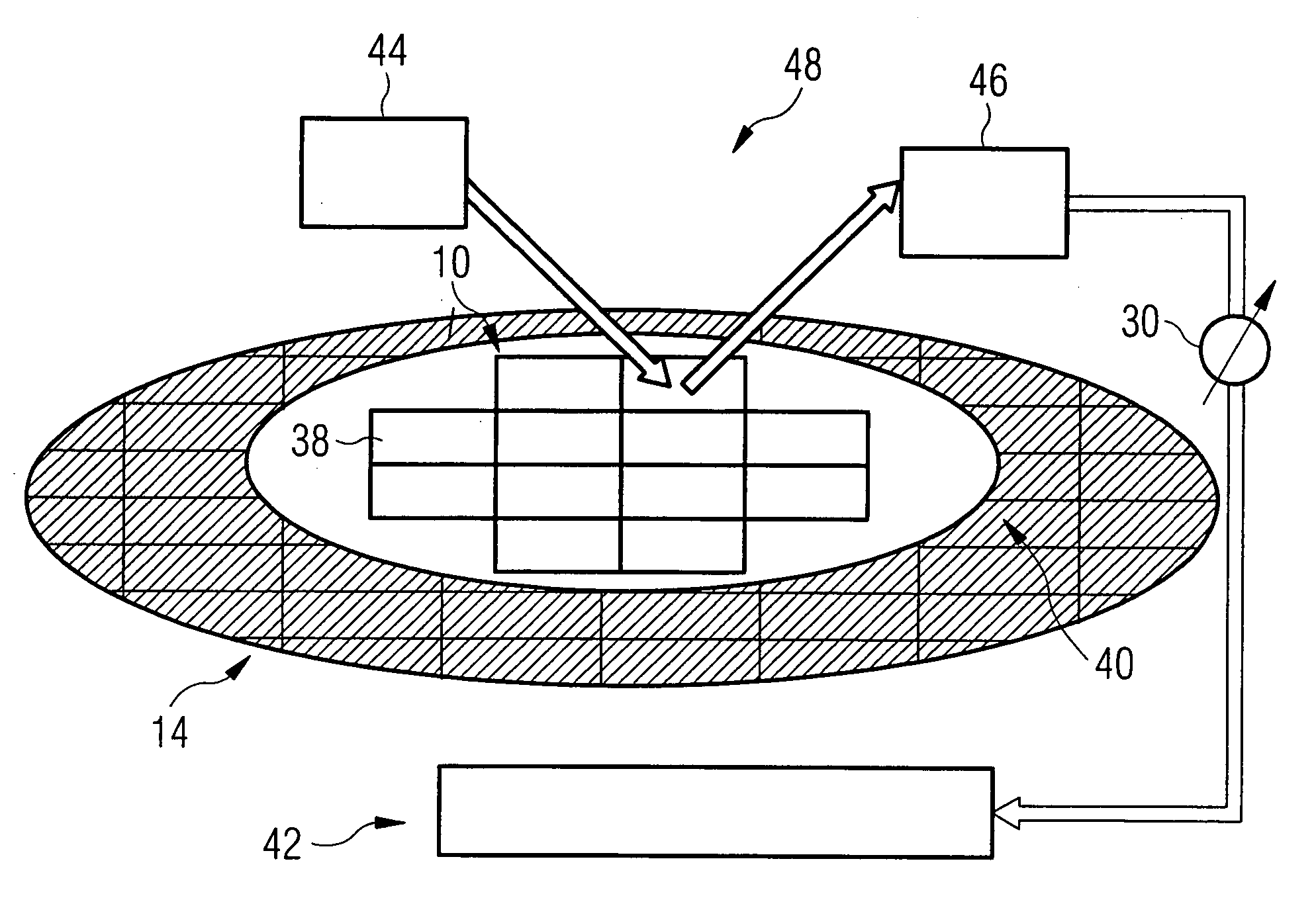
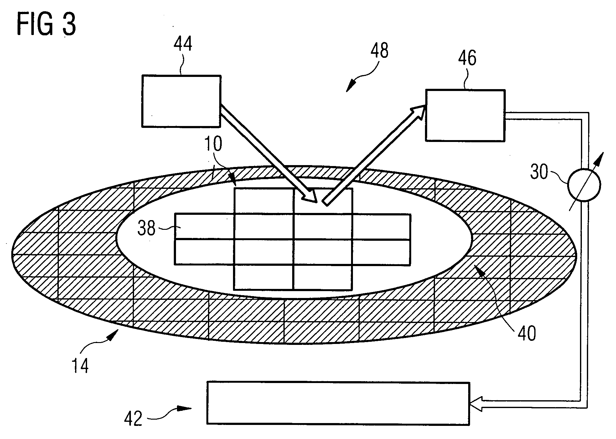
[0038] The invention is explained below by way of example on the basis of an exposure device for immersion lithography and on the basis of a method for monitoring parameters of the exposure device for immersion lithography for producing an integrated circuit. However, the invention can also be applied to the production of other objects in the case of which the intention is to effect patterning with a pattern with a very high resolution.

[0039]FIG. 1 shows an exposure device 5 for immersion lithography. The exposure device 5 includes a substrate holder 14, on which a semiconductor wafer 10 is placed. The semiconductor wafer 10 is provided with a resist layer 16 on a front side 12 of the semiconductor wafer. The resist layer 16 is applied by spinning-on, by way of example. The exposure device 5 further includes a lens 20, which projects light from a light source 32 onto the resist layer 16 of the semiconductor wafer 10. The light source 32 emits light having a wavelength of 248 nm or ...


PUM


Abstract

A method for monitoring parameters of an exposure device for immersion lithography and an exposure device for immersion lithography are provided. In the course of the immersion lithography, the immersion liquid is fed to an analysis device as early as during the exposure. Alterations of the immersion liquid are detected during the exposure process on the basis of a comparison with desired values. The triggering of a warning signal indicates the deviations of the parameters of alterations of the immersion liquid from the associated desired values.

Description

CROSS-REFERNCE TO RELATED APPLICATIONS [0001] This application claims priority under 35 U.S.C. § 119 to German Application No. DE 10 2004 050 642.6, filed on Oct. 18, 2004 and titled “Method for Monitoring Parameters of An Exposure Device for Immersion Lithography, and Exposure Device for Immersion Lithography,” the entire contents of which are hereby incorporated by reference. FIELD OF THE INVENTION [0002] The invention relates to an exposure device for immersion lithography and a method for monitoring parameters of an exposure device for immersion lithography BACKGROUND [0003] Integrated circuits are produced by photolithographic projection of patterns onto semiconductor wafers. For this purpose, layers provided with different electrical properties are usually applied on semiconductor wafers and in each case patterned lithographically. A lithographic patterning step may consist in applying a photosensitive resist, exposing the latter with a desired structure for the relevant layer...

Claims


Application Information

Patent Timeline
IPC IPC(8): G03B27/42
CPCG03B27/42G03F7/70341G03F7/70525
Inventor SCHMIDT, SEBASTIANSCHNEIDER, JENSROESCH, GUILLAUME
Owner POLARIS INNOVATIONS
Why Eureka
Try Eureka