
Joining method and apparatus

a jointing method and jointing technology, applied in the direction of slendering apparatus, manufacturing tools, cooking vessels, etc., can solve the problems of strain, distortion or material deterioration of the members to be joined, incur equipment costs, and complicated and tiresome joining steps, so as to achieve high quality joining, practical cost, and avoid applying a high temperature or a great compressive load

Inactive Publication Date: 2006-04-13
EBARA CORP
View PDF2 Cites 19 Cited by
  • Summary
  • Abstract
  • Description
  • Claims
  • Application Information

AI Technical Summary

Benefits of technology

[0016] The present invention has been accomplished in light of the above-described circumstances. It is an object of the invention to provide a joining method and a joining apparatus which can perform high quality joining at a practical cost, without applying a high temperature or a great compressive load, and without interposing a metal oxide or the like between members to be joined.

Problems solved by technology

The use of these processes, therefore, poses the problem of strain, distortion or material deterioration of the members to be joined, due to large-scale plastic deformation or a high temperature.
This requires a large-scale apparatus, incurs equipment costs, and tends to render the joining step complicated and tiresome.
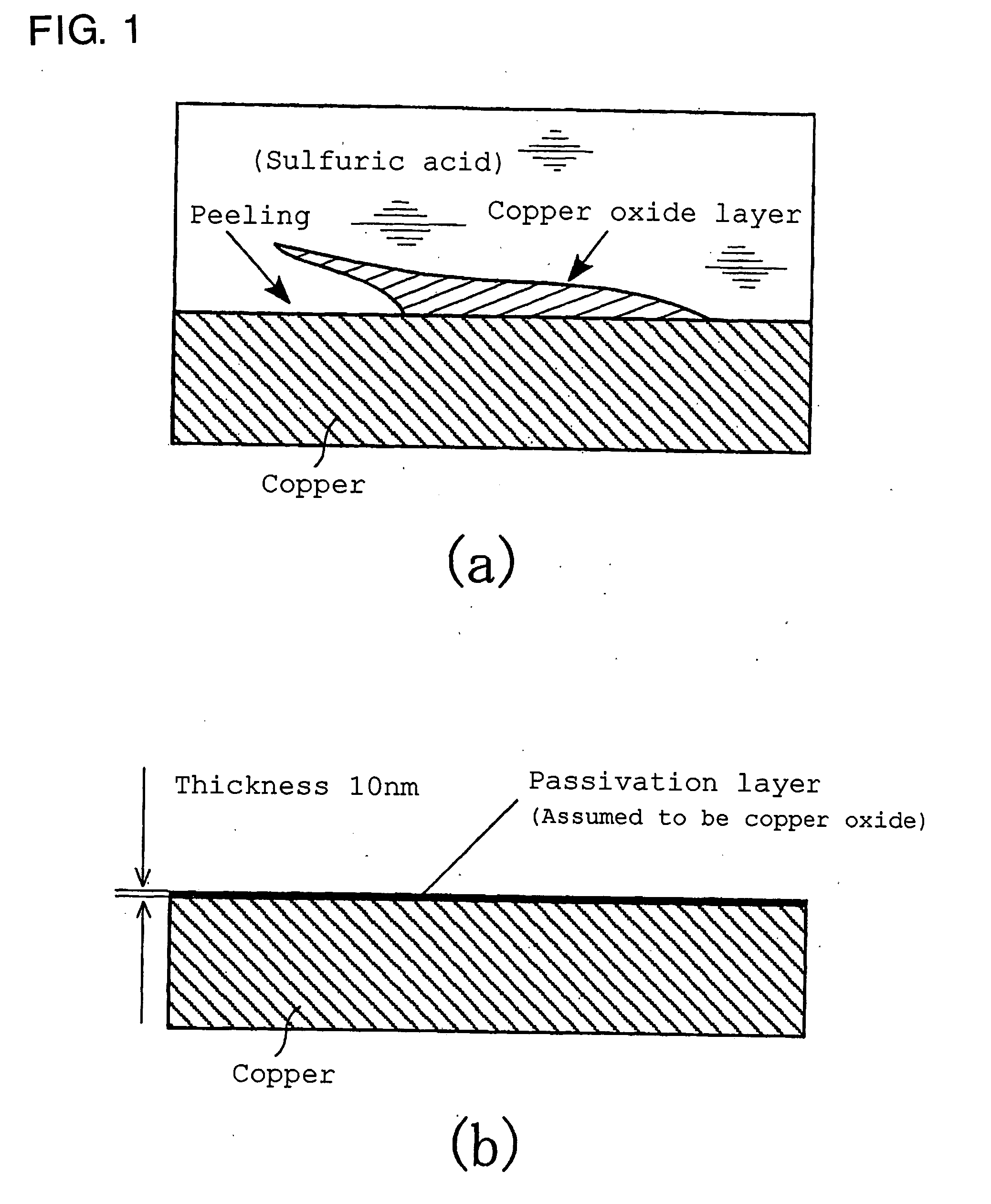
Normally, however, a very thin passivation layer, such as an oxide film, is newly formed on the surface of the metal as a result of surface corrosion by acid pickling.
Upon joining of metal surfaces cleaned by such a method, therefore, metal oxides are interposed between these metal surfaces, posing the problem that sufficient joining strength is not obtained.
This means that the surface is retained in a substantially constant state, and the film cannot be removed.
Furthermore, H(hfac) is the same as a by-product gas produced during CVD process of copper, and is remarkably expensive.
This is likely to damage the surrounding insulating film, for example.
Thus, this method is judged to be unsuitable for the production of a semiconductor device.
Moreover, if the above-mentioned joining method is used in a semiconductor manufacturing process, a compound film, such as a very thin oxide film, has been shown to exert an extremely adverse influence at the time of joining.
Such a great compressive load is inappropriate, because it deforms the members to be joined, on a large scale, and is thus likely to impair the function of the resulting product easily.

Method used


Image

  • Joining method and apparatus
  • Joining method and apparatus
  • Joining method and apparatus

Examples


example

[0070] Two 0.6 mm thick copper plates were kept in contact with formic acid as an organic acid for 10 s by use of the apparatus described in FIG. 5, whereby the copper plates were cleaned. Two copper plates with their metal surfaces exposed were used as members W1, W2 to be joined, and pressure-welded at a temperature of 120° C., as shown in FIG. 11, to form a lap joint. The pressure welding was performed, with a contact surface pressure P being varied in the range of 5 to 50 MPa. The resulting joint was pulled in longitudinal directions to conduct a shear fracture test. The relationship between the contact surface pressure P and the shear joining strength p is shown in FIG. 12. For comparison, data are also plotted for joined specimens which were prepared by joining under the same conditions, except that sulfuric acid for use in ordinary acid pickling was used as a surface treatment liquid for pretreatment before joining in FIG. 12.

[0071] In the Example embodying the present inven...


PUM

PropertyMeasurementUnit
temperatureaaaaaaaaaa
thicknessaaaaaaaaaa
temperatureaaaaaaaaaa

Abstract

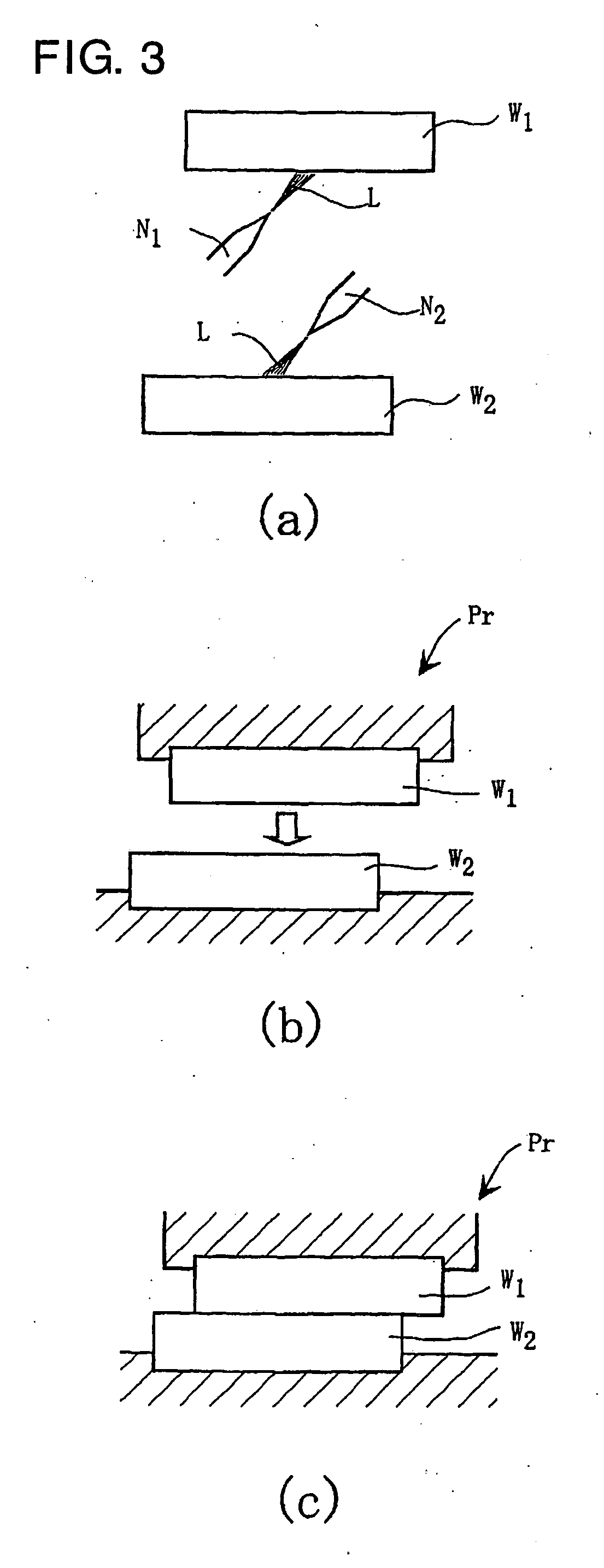
A joining method, which can perform high quality joining at a practical cost, without applying a high temperature or a great compressive load, and without introducing a joining inhibitor, such as a metal oxide, between members to be joined, is provided. This joining method has a joining step of bonding together a plurality of members W1, W2, which are to be joined, metallurgically in a solid phase state, and comprises a contact step of bringing a liquid organic acid L into contact with surfaces to be joined of the members W1, W2 to be joined. By this measure, a non-metallic substance, such as an oxide, covering the surfaces to be joined of the members W1, W2 to be joined is reduced, and thereby converted into a water-soluble complex for removal, whereby metals as materials are exposed at the surfaces to be joined of the members W1, W2 to be joined. Such surfaces to be joined are contacted with each other, whereby the members W1, W2 to be joined can be joined together at a low contact surface pressure and a low temperature.

Description

BACKGROUND OF THE INVENTION [0001] This invention relates to a joining method and apparatus for contacting members, which are to be joined, with each other to cause their metallurgical joining, thereby integrating the members to be joined. [0002] In a manufacturing process, especially a packaging process, for a semiconductor device, solder which contains lead has been frequently used to join contacts together. However, direct joining using no solder is desired in order to lessen a burden on the environment, and further to reduce costs by cutting down on materials and steps. [0003] Table 1 shows conventional methods for joining members to be joined, the members comprising metals or the like, into contact with each other, unchanged as solids, without using solder, thereby binding them metallurgically for integration. TABLE 1Type of joiningMain mechanism · principle · feature of joiningPressure weldingExposure and mutual contact of clean metalsurfaces by plastic deformationDiffusion j...

Claims


Application Information

Patent Timeline
Patent Type & Authority Applications(United States)
IPC IPC(8): A47J36/02
CPCB23K20/02B23K20/24B23K35/007H01L21/67092H01L24/27H01L24/29H01L24/83H01L2224/29339H01L2224/83801H01L2224/8384H01L2924/01005H01L2924/01011H01L2924/01013H01L2924/01015H01L2924/01025H01L2924/01027H01L2924/01029H01L2924/01042H01L2924/01047H01L2924/01059H01L2924/01074H01L2924/01078H01L2924/01082H01L24/75H01L2924/01006H01L2924/01019H01L2924/01033H01L2924/014H01L2224/29101H01L2924/00H01L2924/3512H01L2924/15747H01L2224/7901
Inventor OGURE, NAOAKICHIKAMORI, YUSUKE
Owner EBARA CORP
Learn More